Asus H110M-E H110M-E Users manual English - Page 12
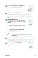
Serial ATA 6.0Gb/s connectors 7-pin SATA6G_1~4, Clear RTC RAM 2-pin CLRTC - front panel
 |
View all Asus H110M-E manuals
Add to My Manuals
Save this manual to your list of manuals |
Page 12 highlights
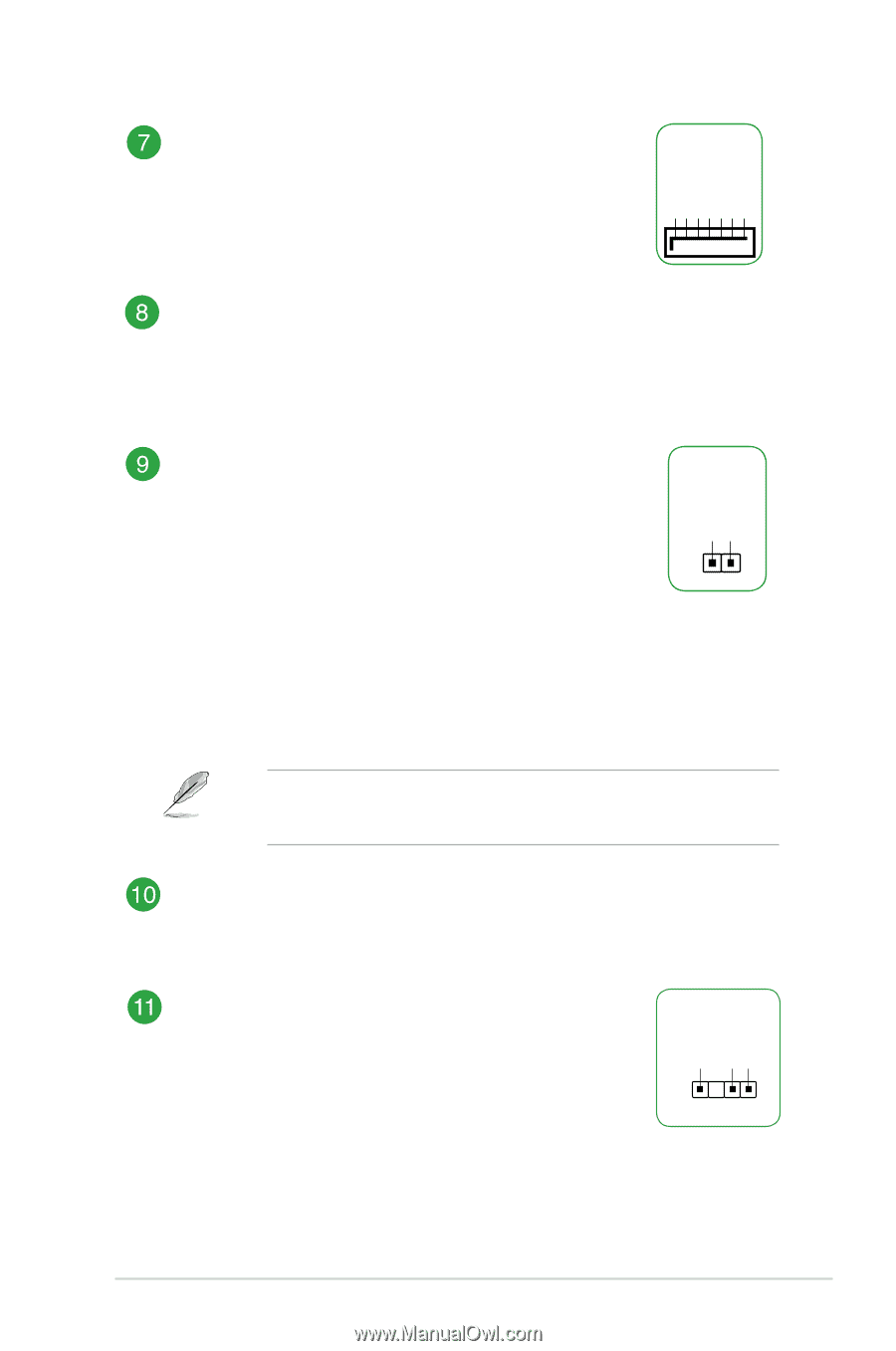
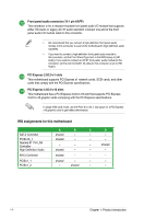
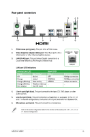
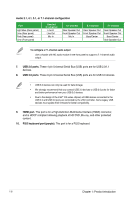
GND RSATA_RXP4 RSATA_RXN4 GND RSATA_TXN4 RSATA_TXP4 GND Serial ATA 6.0Gb/s connectors (7-pin SATA6G_1~4) These connectors connect to Serial ATA 6.0 Gb/s hard disk drives via Serial ATA 6.0 Gb/s signal cables. SATA6G USB 3.0 connectors (20-1 pin USB3_12) Connect a USB 3.0 module to any this connector for additional USB 3.0 front or rear panel ports. This connector complies with USB 3.0 specifications and provide faster data transfer speeds of up to 5 Gbps, faster charging time for USBchargeable devices, optimized power efficiency, and backward compatibility with USB 2.0. Clear RTC RAM (2-pin CLRTC) This header allows you to clear the CMOS RTC RAM data of the system setup information such as date, time, and system passwords. To erase the RTC RAM: 1. Turn OFF the computer and unplug the power cord. 2. Use a metal object such as a screwdriver to short the two pins. 3. Plug the power cord and turn ON the computer. 4. Hold down the key during the boot process and enter BIOS setup to re-enter data. +3V_BAT GND CLRTC PIN 1 If the steps above do not help, remove the onboard battery and short the two pins again to clear the CMOS RTC RAM data. After clearing the CMOS, reinstall the battery. USB 2.0 connectors (10-1 pin USB56 USB910) Connect the USB module cable to any of these connectors, then install the module to a slot opening at the back of the system chassis. These USB connectors comply with USB 2.0 specifications and supports up to 480Mbps connection speed. Digital audio connector (4-1 pin SPDIF_OUT) Connect the S/PDIF Out module cable to this connector, then install the module to a slot opening at the back of the system chassis. +5V SPDIFOUT GND PIN 1 SPDIF_OUT ASUS H110M-E 1-3
-
 1
1 -
2
-
3
-
4
-
5
-
6
-
 7
7 -
 8
8 -
 9
9 -
 10
10 -
 11
11 -
 12
12 -
 13
13 -
 14
14 -
 15
15 -
 16
16 -
 17
17 -
18
-
19
-
20
-
21
-
22
-
23
-
24
-
25
-
26
 |
 |