Asus H110T/CSM Users manual English - Page 11
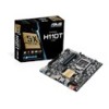
Display panel VCC power selector VCC_PWR_SEL, LGA1151 CPU socket
 |
View all Asus H110T/CSM manuals
Add to My Manuals
Save this manual to your list of manuals |
Page 11 highlights
System panel connector (10-1 pin PANEL) This connector supports several chassis-mounted functions. Speaker connector (4-pin SPEAKER) This 4-pin connector is for the chassis-mounted system warning speaker. The speaker allows you to hear system beeps and warnings. Display panel VCC power selector (VCC_PWR_SEL) VCC_PWR_SEL 1 3V (Default) 2 5V 3 12V Pins 1 (Default) 2 3 Setting 3V 5V 12V LVDS connector This connector is for an LCD monitor that supports Low-voltage Differential Signaling (LVDS) interface. Flat panel display brightness connector (8-pin LCD_BLKT_PANEL) This connector is for the LCD panel backlight and brightness controls. It enables the LCD panel backlight, provides backlight control signals, and provides brightness control signals for the brightness button on the front panel. Display panel backlight power selector (3-pin BLKT_PWR_SEL) BLKT_PWR_SEL 12 23 12V 19V (Default) Pins 1-2 (Default) 2-3 Setting 12V 19V Intel® LGA1151 CPU socket Install Intel® LGA1151 CPU into this surface mount LGA1151 socket, which is designed for 6th Generation Intel® Core™ i7 / i5 / i3, Pentium®, and Celeron® processors For more details, refer to Central Processing Unit (CPU). Chassis intrusion header (4-1 pin CHASSIS) This header is for a chassis-mounted intrusion detection sensor or switch. Connect one end of the chassis intrusion sensor or switch cable to this header. The chassis intrusion sensor or switch sends a high-level signal to this header when a chassis component is removed or replaced. The signal is then generated as a chassis intrusion event. By default, the pin labeled "Chassis Signal" and "Ground" are shorted with a jumper cap. Remove the jumper caps only when you intend to use the chassis intrusion detection feature. ASUS H110T 1-3
-
 1
1 -
2
-
3
-
4
-
5
-
 6
6 -
 7
7 -
 8
8 -
 9
9 -
 10
10 -
 11
11 -
 12
12 -
 13
13 -
 14
14 -
 15
15 -
 16
16 -
17
-
18
-
19
-
20
-
21
-
22
-
23
-
24
-
25
-
26
-
27
-
28
 |
 |
