Asus H610I-EM-A User Manual English - Page 10
Motherboard layout, CAUTION
 |
View all Asus H610I-EM-A manuals
Add to My Manuals
Save this manual to your list of manuals |
Page 10 highlights
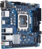
2.2 Motherboard layout NOTE: Place nine screws into the holes indicated by circles to secure the motherboard to the chassis. CAUTION! Do not overtighten the screws! Doing so can damage the motherboard. 26 25 Place this side towards the rear of the chassis 24 23 22 COM2 COM1 LVDS_EDP 1 2 3 45 6 7 LCD_BLKT_PANEL 17.0cm(6.7in) CHASSIS AT_ATX_SEL COM2_SEL COM1_SEL EATX12V PANEL_SW VCC_PWR SEL BKLTEN_SEL COM3 COM4 COM5 8 9 10 11 12 GPIO_CON SPEAKER Super I/O CPU_FAN F_PANEL COM6 HDMI1_DP EATXPWR DDR4 SO-DIMM_A1 (64bit, 260-pin module) DDR4 SO-DIMM_B1 (64bit, 260-pin module) HDMI2 LAN2_U32G1_34 Intel® I210AT LAN1_U32G1_12 Intel® I219V AUDIO AAFP ALC 897 BATTERY Intel® H610 LGA1700 USB9 128Mb BIOS TPM CLRTC 2280 2260 PCIEX16(G4) 2242 M.2(SOCKET3) PCIE SATA 3.0 X4 V COM_DEBUG M.2(WIFI) M.2(SOCKET3) SATA6G_1 SATA6G_2 CHA_FAN USB78 USB56 17.0cm(6.7in) 13 4 10 14 15 16 21 20 19 18 17 2-2 H610I-EM-A
-
 1
1 -
2
-
3
-
4
-
 5
5 -
 6
6 -
 7
7 -
 8
8 -
 9
9 -
 10
10 -
 11
11 -
 12
12 -
 13
13 -
 14
14 -
 15
15 -
16
-
17
-
18
-
19
-
20
-
21
-
22
-
23
-
24
-
25
-
26
-
27
-
28
-
29
-
30
-
31
-
32
-
33
-
34
-
35
-
36
-
37
-
38
-
39
-
40
-
41
-
42
-
43
-
44
-
45
-
46
-
47
-
48
-
49
-
50
-
51
-
52
-
53
-
54
-
55
 |
 |
