Asus K8N-DL User Guide - Page 31
System memory
 |
View all Asus K8N-DL manuals
Add to My Manuals
Save this manual to your list of manuals |
Page 31 highlights
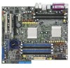
3. When the fan and heatsink assembly is in place, connect the CPU fan cable to the appropriate connector on the motherboard, CPU_FAN1 or CPU_FAN2. CPU_FAN2 CPU_FAN2 Rotation +12V GND ® K8N-DL CPU_FAN1 K8N-DL CPU fan connectors CPU_FAN1 Rotation +12V GND Do not forget to connect the CPU fan connector! Hardware monitoring errors can occur if you fail to plug this connector. 2.4 System memory 2.4.1 Overview The motherboard comes with six 184-pin Double Data Rate (DDR) Dual Inline Memory Modules (DIMM) sockets. The following figure illustrates the location of the sockets: DIMM_A3 DIMM_B3 DIMM_B2 80 Pins DIMM_A2 DIMM_B1 DIMM_A1 104 Pins ® K8N-DL K8N-DL 184-pin DDR DIMM sockets For CPU 1 Channel A Channel B For CPU 2 Channel A Channel B ASUS K8N-DL Sockets DIMM_A1 and DIMM_A2 DIMM_B1 and DIMM_B2 Sockets DIMM_A3 DIMM_B3 2-11
-
 1
1 -
2
-
3
-
4
-
5
-
6
-
7
-
8
-
9
-
10
-
11
-
12
-
13
-
14
-
15
-
16
-
17
-
18
-
19
-
20
-
21
-
22
-
23
-
24
-
25
-
 26
26 -
 27
27 -
 28
28 -
 29
29 -
 30
30 -
 31
31 -
 32
32 -
 33
33 -
 34
34 -
 35
35 -
 36
36 -
37
-
38
-
39
-
40
-
41
-
42
-
43
-
44
-
45
-
46
-
47
-
48
-
49
-
50
-
51
-
52
-
53
-
54
-
55
-
56
-
57
-
58
-
59
-
60
-
61
-
62
-
63
-
64
-
65
-
66
-
67
-
68
-
69
-
70
-
71
-
72
-
73
-
74
-
75
-
76
-
77
-
78
-
79
-
80
-
81
-
82
-
83
-
84
-
85
-
86
-
87
-
88
-
89
-
90
-
91
-
92
-
93
-
94
-
95
-
96
-
97
-
98
-
99
-
100
-
101
-
102
-
103
-
104
-
105
-
106
-
107
-
108
-
109
-
110
-
111
-
112
 |
 |