Asus KFN4-D16 1U User Guide - Page 51
LAN1 link activity LED 2-pin LAN1_LINKACTLED
 |
View all Asus KFN4-D16 1U manuals
Add to My Manuals
Save this manual to your list of manuals |
Page 51 highlights
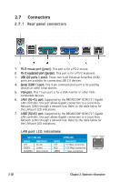
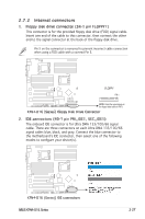
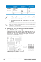
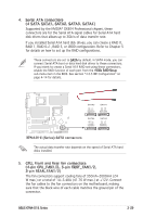
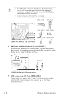
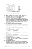
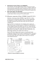
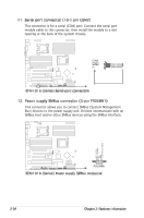
USB+5V USB_P8USB_P8+ GND NC USB+5V USB_P7USB_P7+ GND USB34 KFN4-D16/SAS 1 KFN4-D16 (Series) USB 2.0 connectors 8. System panel auxiliary connector (20-pin AUX_PANEL1) This connector supports several server system functions. • Chassis intrusion connector (3-pin CASE OPEN) This lead is for a chassis with an intrusion detection feature. This requires an external detection mechanism such as a chassis intrusion sensor or microswitch. When you remove any chassis component, the sensor triggers and sends a high level signal to this lead to record a chassis intrusion event. • LAN1 link activity LED (2-pin LAN1_LINKACTLED) This 2-pin connector is for the LAN1 Activity LED. Connect the LAN1 Activity LED cable to this connector. This LED blinks during a network activity and is always lit when linked. • LAN2 link activity LED (2-pin LAN2_LINKACTLED) This 2-pin connector is for the LAN2 Activity LED. Connect the LAN2 Activity LED cable to this connector. This connector blinks during a network activity and lights up when linked. • Locator LED 1 (2-pin LOCATORLED1) This 2-pin connector is for the Locator LED 1. Connect the Locator LED 1 cable to this connector. This LED lights up when the locator button is pressed. • Locator LED 2 (2-pin LOCATORLED2) This 2-pin locator is for the Locator LED 2. Connect the Locator LED 2 cable to this connector. • Locator Button/Switch (2-pin LOCATORBTN) This connector is for the locator button. This button queries the state of the system locator. • Front Panel SMBus (6-1 pin) This connector allows you to connect SMBus (System Management Bus) devices to the system front panel. Devices communicate with an SMBus host and/or other SMBus devices using the SMBus interface. ASUS KFN4-D16 Series 2-31
-
 1
1 -
2
-
3
-
4
-
5
-
6
-
7
-
8
-
9
-
10
-
11
-
12
-
13
-
14
-
15
-
16
-
17
-
18
-
19
-
20
-
21
-
22
-
23
-
24
-
25
-
26
-
27
-
28
-
29
-
30
-
31
-
32
-
33
-
34
-
35
-
36
-
37
-
38
-
39
-
40
-
41
-
42
-
43
-
44
-
45
-
 46
46 -
 47
47 -
 48
48 -
 49
49 -
 50
50 -
 51
51 -
 52
52 -
 53
53 -
 54
54 -
 55
55 -
 56
56 -
57
-
58
-
59
-
60
-
61
-
62
-
63
-
64
-
65
-
66
-
67
-
68
-
69
-
70
-
71
-
72
-
73
-
74
-
75
-
76
-
77
-
78
-
79
-
80
-
81
-
82
-
83
-
84
-
85
-
86
-
87
-
88
-
89
-
90
-
91
-
92
-
93
-
94
-
95
-
96
-
97
-
98
-
99
-
100
-
101
-
102
-
103
-
104
-
105
-
106
-
107
-
108
-
109
-
110
-
111
-
112
-
113
-
114
-
115
-
116
-
117
-
118
-
119
-
120
-
121
-
122
-
123
-
124
-
125
-
126
-
127
-
128
-
129
-
130
-
131
-
132
-
133
-
134
-
135
-
136
-
137
-
138
-
139
-
140
-
141
-
142
 |
 |
