Asus M2N TeleSky Motherboard Installation Guide - Page 51
Front panel audio connector 10-1 pin AAFP, Digital audio connector 4-1 pin SPDIF_OUT
 |
View all Asus M2N TeleSky manuals
Add to My Manuals
Save this manual to your list of manuals |
Page 51 highlights
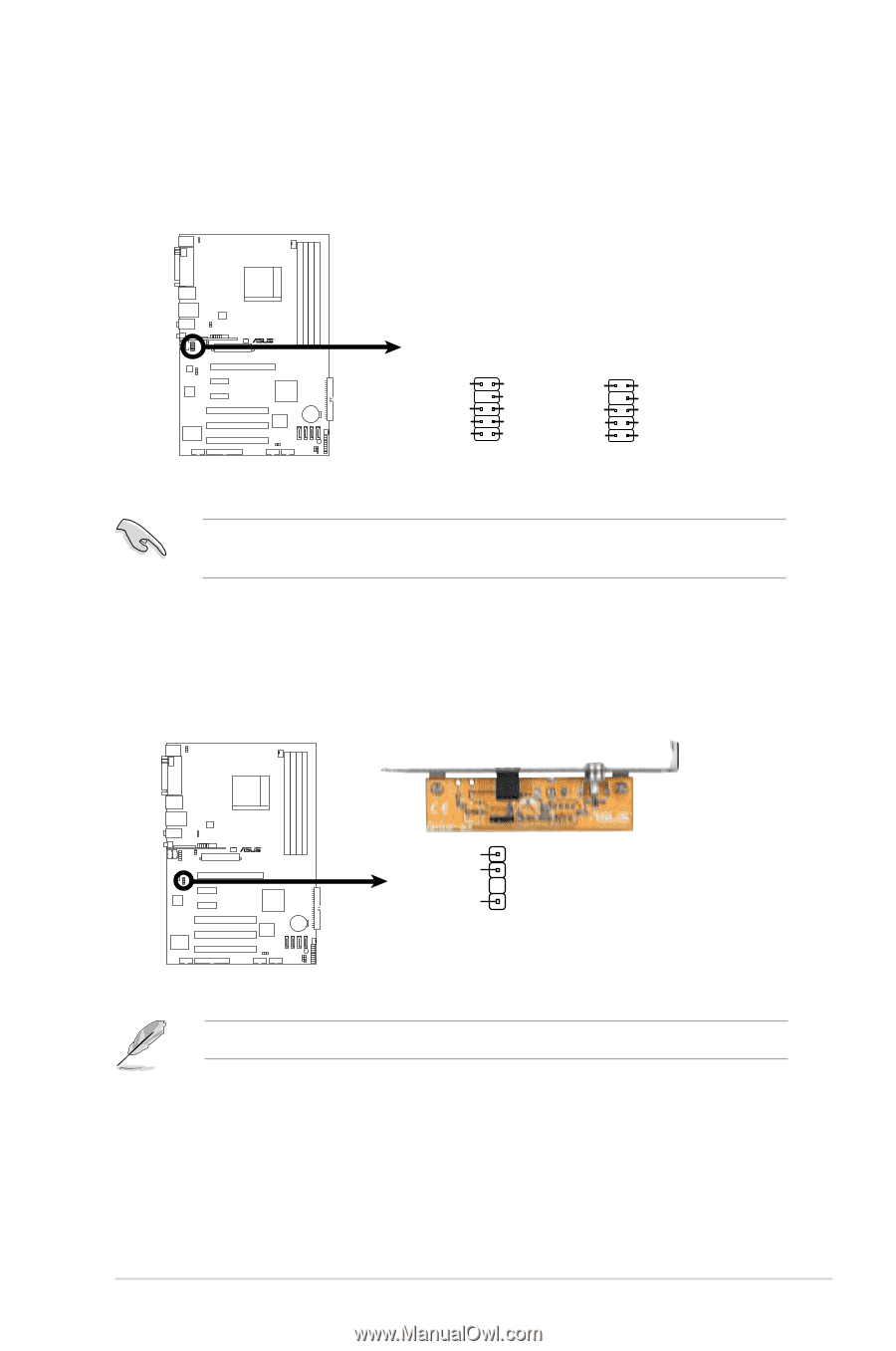
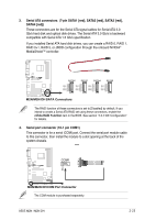
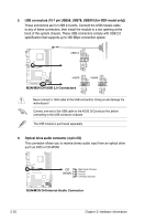
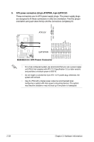
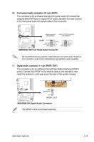
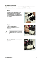
10. Front panel audio connector (10-1 pin AAFP) This connector is for a chassis-mounted front panel audio I/O module that supports either HD Audio or legacy AC`97 audio standard. Connect one end of the front panel audio I/O module cable to this connector. Azalia-compliant Legacy AC'97-compliant R pin definition pin definition AAFP HP_HD MIC2_JD PRESENSE# AGND HP_L Jack_Sense HP_R MIC2_R MIC2_L NC NC NC AGND M2N/M2N DH Front Panel Audio Connector Line out_L NC Line out_R MIC2_R MIC2_L We recommend that you connect a high-definition front panel audio module to this connector to avail of the motherboard's high-definition audio capability. 11. Digital audio connector (4-1 pin SPDIF_OUT) This connector is for an additional Sony/Philips Digital Interface (S/PDIF) port(s). Connect the S/PDIF In/Out module cable to this connector, then install the module to a slot opening at the back of the system chassis. R GND SPDIFOUT +5V SPDIF_OUT M2N/M2N DH Digital Audio Connector The S/PDIF module is purchased separately. ASUS M2N / M2N DH 2-29
-
 1
1 -
2
-
3
-
4
-
5
-
6
-
7
-
8
-
9
-
10
-
11
-
12
-
13
-
14
-
15
-
16
-
17
-
18
-
19
-
20
-
21
-
22
-
23
-
24
-
25
-
26
-
27
-
28
-
29
-
30
-
31
-
32
-
33
-
34
-
35
-
36
-
37
-
38
-
39
-
40
-
41
-
42
-
43
-
44
-
45
-
 46
46 -
 47
47 -
 48
48 -
 49
49 -
 50
50 -
 51
51 -
 52
52 -
 53
53 -
 54
54 -
 55
55 -
 56
56 -
57
-
58
-
59
-
60
-
61
-
62
-
63
-
64
-
65
-
66
-
67
-
68
-
69
-
70
-
71
-
72
-
73
-
74
-
75
-
76
-
77
-
78
-
79
-
80
-
81
-
82
-
83
-
84
-
85
-
86
-
87
-
88
-
89
-
90
-
91
-
92
-
93
-
94
-
95
-
96
-
97
-
98
-
99
-
100
-
101
-
102
-
103
-
104
-
105
-
106
-
107
-
108
-
109
-
110
-
111
-
112
-
113
-
114
-
115
-
116
 |
 |