Asus M4N68T User Manual
Asus M4N68T Manual
 |
View all Asus M4N68T manuals
Add to My Manuals
Save this manual to your list of manuals |
Asus M4N68T manual content summary:
- Asus M4N68T | User Manual - Page 1
M4N68T Motherboard - Asus M4N68T | User Manual - Page 2
purposes, without the express written permission of ASUSTeK Computer Inc. ("ASUS"). Product warranty or service will not be ASUS HAS BEEN ADVISED OF THE POSSIBILITY OF SUCH DAMAGES ARISING FROM ANY DEFECT OR ERROR IN THIS MANUAL OR PRODUCT. SPECIFICATIONS AND INFORMATION CONTAINED IN THIS MANUAL - Asus M4N68T | User Manual - Page 3
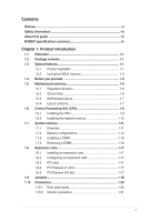
vii About this guide vii M4N68T specifications summary ix Chapter 1: Product introduction 1.1 Welcome 1-1 1.2 Package contents 1-1 1.3 Special features 1-1 1.3.1 Product highlights 1-1 1.3.2 Innovative ASUS features 1-3 1.4 Before you proceed 1-5 1.5 Motherboard overview 1-6 1.5.1 Placement - Asus M4N68T | User Manual - Page 4
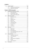
Software support 1-28 1.11.1 Installing an operating system 1-28 1.11.2 Support DVD information 1-28 Chapter 2: BIOS information 2.1 Managing and updating your BIOS 2-1 2.1.1 ASUS Update utility 2-1 2.1.2 ASUS EZ Flash 2 utility 2-2 2.1.3 ASUS CrashFree BIOS utility 2-3 2.2 BIOS CPU - Asus M4N68T | User Manual - Page 5
APIC Support 2-16 2.5.4 APM Configuration 2-16 2.5.5 HW Monitor Configuration 2-17 2.6 Boot menu 2-18 2.6.1 Boot Device Priority 2-18 2.6.2 Boot Settings Configuration 2-18 2.6.3 Security 2-19 2.7 Tools menu 2-21 2.7.1 ASUS EZ Flash 2 2-21 2.7.2 Express Gate 2-21 2.7.3 ASUS O.C. Profile - Asus M4N68T | User Manual - Page 6
accordance with manufacturer's instructions, may cause harmful of the monitor to the graphics card is required to assure compliance ASUS REACH website at http://green.asus.com/english/REACH.htm. DO NOT throw the motherboard NOT throw the mercury-containing button cell battery in municipal waste - Asus M4N68T | User Manual - Page 7
. • If you encounter technical problems with the product, contact a qualified service technician or your retailer. About this guide This user guide contains the information you need when installing and configuring the motherboard. How this guide is organized This guide contains the following parts - Asus M4N68T | User Manual - Page 8
guide To ensure that you perform certain tasks properly, take note of the following symbols used throughout this manual Instructions software updates. 1. ASUS websites The ASUS website provides updated information on ASUS hardware and software products. Refer to the ASUS it�e�m�t�o�s�e�le�c�t. - Asus M4N68T | User Manual - Page 9
LAN Audio USB Back panel I/O ports AMD® Socket AM3 for AMD® Phenom™ II / Athlon™ II / Sempron™ 100 series processors AMD® Cool 'n' Quiet™ Technology AMD 64 architecture enables simultaneous 32-bit and 64-bit computing * Refer to www.asus.com for the AMD® CPU support list NVIDIA® nForce 630a 2000 - Asus M4N68T | User Manual - Page 10
at 1MHz increment ASUS C.P.R. (CPU Parameter Recall) 2 x Serial ATA cables 1 x Ultra DMA 133/100 cable 1 x I/O shield 1 x User Manual Drivers ASUS Update ASUS PC Probe II Anti-Virus software (OEM version) ATX form factor: 12 in x 8.2 in (30.5 cm x 20.8 cm) *Specifications are subject to change - Asus M4N68T | User Manual - Page 11
II / Athlon™ II / Sempron™ 100 series CPU support This motherboard supports AMD® Socket AM3 multi-core processors with unique L3 cache and delivers better overclocking capabilities with less power consumption. It features dual-channel DDR3 1333 memory support and accelerates data transfer rate up to - Asus M4N68T | User Manual - Page 12
DDR3 1800 (O.C.) support This motherboard supports DDR3 memory that features data transfer rates of 1800 (O.C.)/1600 (O.C.)/1333/1066 MHz to meet the higher bandwidth requirements of the latest operating system, 3D graphics, multimedia, and Internet applications. Gigabit LAN solution The onboard LAN - Asus M4N68T | User Manual - Page 13
contains the BIOS file. ASUS EZ Flash 2 ASUS EZ Flash 2 allows you to update the BIOS from a USB flash disk before entering the OS. ASUS Q-Fan ASUS Q-Fan technology intelligently adjusts the CPU fan speed according to system loading to ensure a quiet, cool, and efficient operation. ASUS M4N68T 1-3 - Asus M4N68T | User Manual - Page 14
the system chassis and clear the RTC data. Simply shut down and reboot the system, and the BIOS automatically restores the CPU parameters to their default settings. Green ASUS This motherboard and its packaging comply with the European Union's Restriction on the use of Hazardous Substances (RoHS - Asus M4N68T | User Manual - Page 15
you install motherboard components or change any motherboard settings. • Unplug the power cord from the wall socket before touching motherboard component. The illustration below shows the location of the onboard LED. M4N68T SB_PWR M4N68T Onboard LED ON OFF Standby Power Powered Off ASUS M4N68T - Asus M4N68T | User Manual - Page 16
overview 1.5.1 Placement direction When installing the motherboard, ensure that you place it into the chassis in the correct orientation. Screw holes Place six screws into the holes indicated by circles to secure the motherboard to the chassis. DO NOT overtighten the screws! Doing so can damage the - Asus M4N68T | User Manual - Page 17
USB910) 5. AMD CPU socket 1-8 13. Digital audio connector (4-1 pin SPDIF_OUT) 1-27 6. DDR3 DIMM sockets 1-11 14. Front panel audio connector (10-1 pin AAFP) 1-21 7. Onboard LED 1-5 15. Internal speaker connector (4- pin SPEAKER) 1-24 8. IDE connector (40-1 pin PRI_IDE) 1-23 ASUS M4N68T 1-7 - Asus M4N68T | User Manual - Page 18
pinout from the the AM2+/AM2 socket. Ensure that you use a CPU designed for the AM3 socket. 1.6.1 Installing the CPU To install a CPU: 1. Locate the CPU socket on the motherboard. M4N68T M4N68T CPU socket AM3 2. Press the lever sideways to unlock the Socket lever socket, then lift it up to a 90 - Asus M4N68T | User Manual - Page 19
. 7. Connect the CPU fan cable to the CPU_FAN connector on the motherboard. M4N68T CPU_FAN CPU FAN PWM CPU FAN IN CPU FAN PWR GND M4N68T CPU fan connector DO NOT forget to connect the CPU fan connector! Hardware monitoring errors can occur if you fail to plug this connector. ASUS M4N68T 1-9 - Asus M4N68T | User Manual - Page 20
remove the retention module base when installing the CPU or installing other motherboard components. • If you purchased a separate CPU heatsink and fan assembly, ensure that a Thermal Interface Material is properly applied to the CPU heatsink or CPU before you install the heatsink and fan assembly - Asus M4N68T | User Manual - Page 21
Data Rate 3 (DDR3) Dual Inline Memory Modules (DIMM) sockets. The figure illustrates the location of the DDR3 DIMM sockets: DIMM_A2 DIMM_B2 DIMM_A1 DIMM_B1 M4N68T Channel Channel A Channel B Sockets DIMM_A1 and DIMM_A2 DIMM_B1 and DIMM_B2 M4N68T 240-pin DDR3 DIMM sockets ASUS M4N68T 1-11 - Asus M4N68T | User Manual - Page 22
�W�i�nd�o�w��s® OS if you want to install 4GB or more memory on the motherboard. • This motherboard does not support DIMMs made up of 256 megabits (Mb) chips or less. M4N68T Motherboard Qualified Vendors Lists (QVL) DDR3-1866(O.C.)MHz capability Vendor Part No. Kingston KHX14900D3K3/3GX(XMP - Asus M4N68T | User Manual - Page 23
CL N/A N/A 9 9 N/A N/A 9 N/A 6-6-6-20 9 6-6-6-20 9 N/A N/A 7-7-7-18 9-9-9-24 N/A DIMM support A* B* C* • • • • • • • • • • • • • • • • • • • • • • • • • • • • • • • • • • • • • • • • • • • • • • • • (continued on the next page) ASUS M4N68T 1-13 - Asus M4N68T | User Manual - Page 24
(Kit of 3) DS GEIL DDR3-1333 CL9-9-9-24 1024MB SS GEIL GV34GB1333C7DC 2048MB DS GEIL DDR3-1333 CL9-9-9-24 6144MB(Kit of N/A N/A N/A N/A N/A 8-8-8-24 N/A N/A N/A N/A N/A 9 N/A 7-7-7-20 8-8-8-24 DIMM support A* B* C • •• • •• • •• • •• 1-14 Chapter 1: Product introduction - Asus M4N68T | User Manual - Page 25
DDR3-1066MHz capability Vendor Part No. Size SS/ Chip DS memory configuration. • C*: Supports two pairs of modules inserted into both the blue slots and the black slots as two pairs of dual-channel memory configuration. Visit the ASUS website at www.asus.com for the latest QVL. ASUS M4N68T - Asus M4N68T | User Manual - Page 26
before adding or removing DIMMs or other system components. Failure to do so can cause severe damage to both the motherboard and the components. 1. Press the retaining clips outward to unlock a DIMM socket. 2. Align a DIMM on the socket such that the notch on the DIMM matches the break on the - Asus M4N68T | User Manual - Page 27
PCI Express x1 slots This motherboard supports PCI Express x1 network cards, SCSI cards, and other cards that comply with the PCI Express specifications. 1.8.5 PCI Express x16 slot This motherboard supports a PCI Express x16 graphics card that comply with the PCI Express specifications. ASUS M4N68T - Asus M4N68T | User Manual - Page 28
Real Time Clock (RTC) RAM in CMOS. You can clear the CMOS memory of date, time, and system setup parameters by erasing the CMOS RTC RAM data. The onboard button cell battery powers the RAM data in CMOS, which include system setup information such as system passwords. M4N68T CLRTC 12 23 Normal - Asus M4N68T | User Manual - Page 29
) Set these jumpers to +5V to wake up the computer from S1 sleep mode (CPU stopped, DRAM refreshed, system running in low power mode) using the connected USB devices and a corresponding setting in the BIOS. KBPWR 12 23 +5V +5VSB (Default) M4N68T M4N68T Keyboard Power Setting ASUS M4N68T 1-19 - Asus M4N68T | User Manual - Page 30
Status OFF ORANGE GREEN Description 10Mbps connection 100Mbps connection 1Gbps connection ACT/LINK SPEED LED LED LAN port 4. Line In port (light blue). This port connects to the tape, CD, HD audio module in the front panel to support 8-channel audio output. 1-20 Chapter 1: Product introduction - Asus M4N68T | User Manual - Page 31
mounted front panel audio I/O module that supports either High Definition Audio or AC` this connector to avail of the motherboard high-definition audio capability. • BIOS to [HD Audio]. See section 2.4.3 Chipset for details. • The front panel audio I/O module is purchased separately. ASUS M4N68T 1- - Asus M4N68T | User Manual - Page 32
firmly until the connectors completely fit. ATX12V EATXPWR +12V DC +12V DC M4N68T GND GND +3 Volts +12 Volts +12 Volts +5V Standby Power OK Recommended Power Supply Wattage Calculator at http://support.asus. com/PowerSupplyCalculator/PSCalculator.aspx?SLanguage=en-us for - Asus M4N68T | User Manual - Page 33
cable: blue, black, and gray. Connect the blue connector to the motherboard's IDE connector, then select one of the following modes to configure your the same setting. M4N68T PRI_IDE M4N68T IDE connector PIN1 NOTE:Orient the red markings on the IDE ribbon cable to PIN 1. ASUS M4N68T 1-23 - Asus M4N68T | User Manual - Page 34
3Gb/s is backward compatible with Serial ATA 1.5Gb/s specification. The data transfer M4N68T SATA connectors • Install the Windows® XP Service Pack 2 or later versions before using Serial ATA. • The motherboard the RAID Supplementary Guide included in the folder named Manual in the support DVD. 5. - Asus M4N68T | User Manual - Page 35
data is read from or written to the HDD. • Power/Soft-off button (2-pin PWRBTN) This 2-pin connector is for the system power button. • Reset button (2-pin RESET) This 2-pin connector is for the chassis-mounted reset button for system reboot without turning off the system power. ASUS M4N68T 1-25 - Asus M4N68T | User Manual - Page 36
the system chassis. These USB connectors comply with USB 2.0 specification that supports up to 480Mbps connection speed. USB+5V USB_P6USB_P6+ GND NC USB 5V USB_P9USB_P9+ GND M4N68T USB2.0 connectors Never connect a 1394 cable to the USB connectors. Doing so will damage the motherboard! The USB 2.0 - Asus M4N68T | User Manual - Page 37
DO NOT forget to connect the fan cables to the fan connectors. Insufficient air flow inside the system may damage the motherboard components. These are not jumpers! DO NOT place jumper caps on the fan connectors. Only the 4-pin CPU fan connector supports the ASUS Q-Fan feature. ASUS M4N68T 1-27 - Asus M4N68T | User Manual - Page 38
contains the drivers, software applications, and utilities that you can install to avail all motherboard features. The contents of the Support DVD are subject to change at any time without notice. Visit the ASUS website at www.asus.com for updates. To run the Support DVD Place the Support DVD into - Asus M4N68T | User Manual - Page 39
is available in the support DVD that comes with the motherboard package. Installing ASUS Update To install ASUS Update: 1. Place the support DVD into the optical drive. The Drivers menu appears. 2. Click the Utilities tab, then click ASUS Update. 3. Follow the onscreen instructions to complete the - Asus M4N68T | User Manual - Page 40
Updating from a BIOS file a. Select Update BIOS from a file, then click Next. b. Locate the BIOS file from the Open window, then click Open. 3. Follow the onscreen instructions to complete the updating process. 2.1.2 ASUS EZ Flash 2 utility The ASUS EZ Flash 2 feature allows you to update the BIOS - Asus M4N68T | User Manual - Page 41
the motherboard support DVD or a removable device that contains the updated BIOS file. • Before using this utility, rename the BIOS file in the removable device into M4N68T.ROM. • The BIOS file in the support DVD may not be the latest version. Download the latest BIOS file from the ASUS website - Asus M4N68T | User Manual - Page 42
from the operating system. • The default BIOS settings for this motherboard apply to most conditions to ensure optimum performance. If the system becomes unstable after changing any BIOS settings, load the default settings to ensure system compatibility and stability. Select the Load Setup Defaults - Asus M4N68T | User Manual - Page 43
menu screen Menu items Menu bar Configuration fields Main Advanced Power BIOS SETUP UTILITY Boot Tools Exit Main Settings System Time [19:34:30] System Date [Fri 11/13/ in the menu and change the settings. Some of the navigation keys differ from one screen to another. ASUS M4N68T 2-5 - Asus M4N68T | User Manual - Page 44
change the value of a field, select it then press to display a list of options. Refer to 2.2.7 Pop-up window. 2.2.7 Pop-up window Select a screen. Main Advanced BIOS SETUP UTILITY Power Boot Tools Exit Suspend Mode ACPI 2.0 Support ACPI APIC support APM Configuration Hardware - Asus M4N68T | User Manual - Page 45
and how to navigate through them. Main Advanced Main Settings Power BIOS SETUP UTILITY Boot Tools Exit System Time [19:34:30] System [SATA1,2,3,4] nVidia RAID Function [Disabled] Enables or disables the nVidia RAID function. Configuration options: [Disabled] [Enabled] ASUS M4N68T 2-7 - Asus M4N68T | User Manual - Page 46
then press to display the IDE/SATA device information. The BIOS automatically detects the values opposite the dimmed items (Device, Vendor, Size, and to the device occurs multiple sectors at a time if the device supports multisector transfer feature. When this item is set to [Disabled], the - Asus M4N68T | User Manual - Page 47
Configuration The items and configuration options in this menu may vary depending on the AMD CPU type. CPU OverClocking [Auto] Selects the CPU overclocking options to achieve desired CPU internal frequency. Configuration options: [Manual] [Auto] [Standard] [Overclock Profile] ASUS M4N68T 2-9 - Asus M4N68T | User Manual - Page 48
The following item only appears when you set CPU Overclocking to [Manual]. CPU/HT Reference Clock (MHz) [200] Sets the CPU/HT Reference Clock. Configuration options: [Min.=200] [Max.=300] The following item only appears when you set CPU Overclocking to [Overclock Profile]. Overclock Options [Auto] - Asus M4N68T | User Manual - Page 49
: [Auto] [Max. = 2.3100V] [Min. = 1.5000V] Chipset Over Voltage [Auto] Sets the chipset over voltage. The values range from 1.20000V to 1.60000V with a 0.01000V increment. Use the / keys to adjust the value. Configuration options: [Auto] [Max. = 1.60000V] [Min. = 1.20000V] ASUS M4N68T 2-11 - Asus M4N68T | User Manual - Page 50
CPU-related information that the BIOS automatically detects. GART Error Reporting [Disabled] This option should remain disabled for the normal operation. The driver developer may enable it for testing purpose. Configuration options: [Disabled] [Enabled] Microcode Updation even though memory slots are - Asus M4N68T | User Manual - Page 51
to set the ECC mode. Configuration options: [Disabled] [Basic] [Good] [Super] [Max] [User] SouthBridge Configuration Primary Graphics Adapter [PCIE -> PCI] Selects the primary display adapter. Configuration options: [PCIE -> PCI] [PCI -> PCIE] Azalia Audio [Auto] Enables or disables the Azalia audio - Asus M4N68T | User Manual - Page 52
or legacy ISA devices, and setting the memory size block for legacy ISA devices. Take caution when changing the settings of the PCI PnP menu items. Incorrect field values can cause the system to malfunction. Plug and Play O/S [No] When this item is set to [No], BIOS configures all the devices in the - Asus M4N68T | User Manual - Page 53
the legacy USB support is disabled. BIOS waits for the USB storage device to initialize. Configuration options: [10 Sec] [20 Sec] [30 Sec] [40 Sec] Emulation Type [Auto] Allows you to set the emulation type. Configuration options: [Auto] [Floppy] [Forced FDD] [Hard Disk] [CDROM] ASUS M4N68T - Asus M4N68T | User Manual - Page 54
], this parameter allows you to wake the system through a PCI Express/ PCI card. This feature requires an ATX power supply that provides at least 1A on the +5VSB lead.�C�o��n�f�ig�u��ra��ti�o�n��o�p��ti�o�n�s��: �[D��i�s�a�b�l�e�d�]��[E��n�a�b��le��d�] Power on By Ring [Disabled] Enables or disables - Asus M4N68T | User Manual - Page 55
Allows you to use specific keys on the motherboard and CPU temperatures. Select Ignored if you do not wish to display the detected temperatures. CPU ASUS Q-Fan feature that smartly adjusts the CPU fan speeds for more efficient system operation. Configuration options: [Disabled] [Enabled] ASUS M4N68T - Asus M4N68T | User Manual - Page 56
• To access Windows OS in Safe Mode, do any of the following: • Press when ASUS logo appears. • Press after POST. 2.6.2 Boot Settings Configuration Quick Boot [Enabled] Enabling this item allows the BIOS to skip some power on self tests (POST) while booting to decrease the time needed - Asus M4N68T | User Manual - Page 57
the display mode for option ROM. Configuration options: [Force BIOS] [Keep Current] Bootup Num-Lock [On] Selects the power-on your BIOS password, you can clear it by erasing the CMOS Real Time Clock (RTC) RAM. See section 1.9 Jumpers for information on how to erase the RTC RAM. ASUS M4N68T 2-19 - Asus M4N68T | User Manual - Page 58
Select this item to clear the user password. Password Check [Setup] When set to [Setup], BIOS checks for user password when accessing the Setup utility. When set to [Always], BIOS checks for user password both when accessing Setup and booting the system. Configuration options: [Setup] [Always - Asus M4N68T | User Manual - Page 59
> to display the sub-menu. Main Advanced Power BIOS SETUP UTILITY Boot Tools Exit ASUS EZ Flash 2 Express Gate Enter OS Timer Reset User Data [Auto] [10 Seconds] [No] Press ENTER to run the utility to select and update BIOS. This utility supports: 1.FAT 12/16/32 (r/w) 2.NTFS (read only) 3.CD - Asus M4N68T | User Manual - Page 60
down or reset the system while updating the BIOS to prevent the system boot failure! • We recommend that you update the BIOS file only coming from the same memory/CPU configuration and BIOS version. • Only the CMO file can be loaded. 2.7.4 AI NET 2 Check Realtek Phy LAN cable [Disabled] Enables or - Asus M4N68T | User Manual - Page 61
program. If you made changes to fields other than System Date, System Time, and Password, the BIOS asks for a confirmation before exiting. Discard Changes This option allows you to discard the selections you or make other changes before saving the values to the non-volatile RAM. ASUS M4N68T 2-23 - Asus M4N68T | User Manual - Page 62
2-24 Chapter 2: BIOS information
-
 1
1 -
 2
2 -
 3
3 -
 4
4 -
 5
5 -
 6
6 -
 7
7 -
8
-
9
-
10
-
11
-
12
-
13
-
14
-
15
-
16
-
17
-
18
-
19
-
20
-
21
-
22
-
23
-
24
-
25
-
26
-
27
-
28
-
29
-
30
-
31
-
32
-
33
-
34
-
35
-
36
-
37
-
38
-
39
-
40
-
41
-
42
-
43
-
44
-
45
-
46
-
47
-
48
-
49
-
50
-
51
-
52
-
53
-
54
-
55
-
56
-
57
-
58
-
59
-
60
-
61
-
62
 |
 |

Motherboard
M4N68T