Asus M5A78L-M USB3 User Manual - Page 21
System memory - connector
 |
View all Asus M5A78L-M USB3 manuals
Add to My Manuals
Save this manual to your list of manuals |
Page 21 highlights
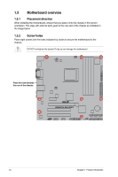
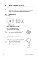
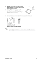
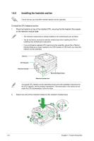
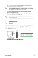
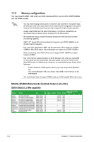
3. Align the other end of the retention bracket to the retention module base. A clicking sound denotes that the retention bracket is in place. Ensure that the fan and heatsink assembly perfectly fits the retention mechanism module base, otherwise you cannot snap the retention bracket in place. 4. Push down the retention bracket lock on the retention mechanism to secure the heatsink and fan to the module base. 5. When the fan and heatsink assembly is in place, connect the CPU fan cable to the connector on the motherboard labeled CPU_FAN. DO NOT forget to connect the CPU fan connector! Hardware monitoring errors can occur if you fail to plug this connector. 1.7 System memory 1.7.1 Overview This motherboard comes with four Double Data Rate 3 (DDR3) Dual Inline Memory Modules (DIMM) sockets. A DDR3 module has the same physical dimensions as a DDR2 DIMM but is notched differently to prevent installation on a DDR2 DIMM socket. DDR3 modules are developed for better performance with less power consumption. The figure illustrates the location of the DDR3 DIMM sockets: DIMM_A1 DIMM_A2 DIMM_B1 DIMM_B2 M5A78L-M/USB3 Channel Channel A Channel B M5A78L-M/USB3 240-pin DDR3 DIMM sockets Sockets DIMM_A1 and DIMM_A2 DIMM_B1 and DIMM_B2 ASUS M5A78L-M/USB3 1-11
-
 1
1 -
2
-
3
-
4
-
5
-
6
-
7
-
8
-
9
-
10
-
11
-
12
-
13
-
14
-
15
-
 16
16 -
 17
17 -
 18
18 -
 19
19 -
 20
20 -
 21
21 -
 22
22 -
 23
23 -
 24
24 -
 25
25 -
 26
26 -
27
-
28
-
29
-
30
-
31
-
32
-
33
-
34
-
35
-
36
-
37
-
38
-
39
-
40
-
41
-
42
-
43
-
44
-
45
-
46
-
47
-
48
-
49
-
50
-
51
-
52
-
53
-
54
-
55
-
56
-
57
-
58
-
59
-
60
-
61
-
62
-
63
-
64
 |
 |