Asus Mini PC PB60G PB60G Users Manual English - Page 13
Left view, Graphics module port, PB60V, Graphics, module, optional
 |
View all Asus Mini PC PB60G manuals
Add to My Manuals
Save this manual to your list of manuals |
Page 13 highlights
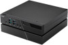
Left view PB60V / PB60G Graphics module (optional) Graphics module port This port allows you to connect the Graphics module with your Mini PC. If the port cover is attached, remove the cover before installing the Graphics module to your Mini PC. Graphics module connector The Graphics module connector is used to connect your Graphics module to your Mini PC. Graphics module lock The Graphics module lock allows you to secure your Graphics module with your Mini PC. Push the lock down to unlock the Graphics module lock before removing the Graphics module from your Mini PC. ASUS Mini PC PB60 Series 13
-
 1
1 -
2
-
3
-
4
-
5
-
6
-
7
-
 8
8 -
 9
9 -
 10
10 -
 11
11 -
 12
12 -
 13
13 -
 14
14 -
 15
15 -
 16
16 -
 17
17 -
 18
18 -
19
-
20
-
21
-
22
-
23
-
24
-
25
-
26
-
27
-
28
-
29
-
30
-
31
-
32
-
33
-
34
-
35
-
36
-
37
-
38
-
39
-
40
-
41
-
42
-
43
-
44
-
45
-
46
-
47
-
48
-
49
-
50
-
51
-
52
 |
 |

ASUS Mini PC PB60 Series
13
Graphics module port
This port allows you to connect the Graphics module with
your Mini PC. If the port cover is attached, remove the
cover before installing the Graphics module to your Mini
PC.
Graphics module connector
The Graphics module connector is used to connect your
Graphics module to your Mini PC.
Graphics module lock
The Graphics module lock allows you to secure your
Graphics module with your Mini PC. Push the lock down
to unlock the Graphics module lock before removing the
Graphics module from your Mini PC.
Left view
PB60V /
PB60G
Graphics
module
(optional)