Asus P1-AH1 P1-AH1 User''s Manual for English Edition - Page 21
Installing a CPU - pundit motherboard
 |
View all Asus P1-AH1 manuals
Add to My Manuals
Save this manual to your list of manuals |
Page 21 highlights
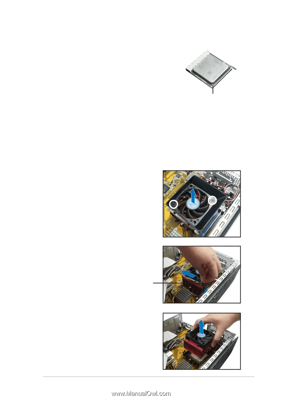
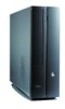
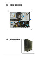
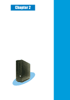
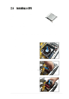
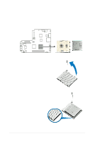
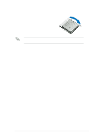
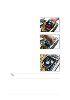
2.6 Installing a CPU The motherboard comes with a surface mount 939-pin Zero Insertion Force (ZIF) socket designed for AMD Athlon® 64 processor. The 128-bit wide data paths of this processor can run applicatoins faster than procesors with only 32- bit or 64-bit wide data paths. Take note of the marked corner (with gold triangle) Gold triangle on the CPU. This mark should match a specific corner on the socket to ensure correct installation. 2.6.1 Removing the CPU fan and heatsink assembly The system package includes a pre-installed proprietary CPU fan and heatsink assembly to provide an efficient thermal solution to the CPU. You need to remove the CPU fan and heatsink assembly to install the CPU. To remove the CPU fan and heatsink assembly: 1. Disconnect the CPU fan cable. 2. Remove two screws securing the blower to the CPU fan. Set the blower aside. 3. Unhook and slide out the metal clips that secure the fan and heatsink assembly to the retention module. Locking lever 4. Lift the CPU fan and heatsink assembly, then set aside. ASUS Pundit P1-AH1 2-5
-
 1
1 -
2
-
3
-
4
-
5
-
6
-
7
-
8
-
9
-
10
-
11
-
12
-
13
-
14
-
15
-
 16
16 -
 17
17 -
 18
18 -
 19
19 -
 20
20 -
 21
21 -
 22
22 -
 23
23 -
 24
24 -
 25
25 -
 26
26 -
27
-
28
-
29
-
30
-
31
-
32
-
33
-
34
-
35
-
36
-
37
-
38
-
39
-
40
-
41
-
42
-
43
-
44
-
45
-
46
-
47
-
48
-
49
-
50
-
51
-
52
-
53
-
54
-
55
-
56
-
57
-
58
-
59
-
60
-
61
-
62
-
63
-
64
-
65
-
66
-
67
-
68
-
69
-
70
-
71
-
72
-
73
-
74
-
75
-
76
-
77
-
78
-
79
-
80
-
81
-
82
-
83
-
84
-
85
-
86
-
87
-
88
-
89
-
90
-
91
-
92
-
93
-
94
 |
 |