Asus P2L97A User Manual - Page 24
ASUS P2L97A User's Manual, Parallel Printer Connector 25-pin Female, Serial Port COM1 Connectors One
 |
View all Asus P2L97A manuals
Add to My Manuals
Save this manual to your list of manuals |
Page 24 highlights
III. INSTALLATION 3. Parallel Printer Connector (25-pin Female) You can enable the parallel port and choose the IRQ through "Onboard Parallel Port" in Chipset Features Setup of the BIOS SOFTWARE. NOTE: Serial printers must be connected to the serial port. Parallel (Printer) Port (25-pin Female) III. INSTALLATION Connectors 4. Serial Port COM1 Connectors (One 9-pin Male) One serial port can be used for pointing devices or other serial devices. See "Onboard Serial Port" in Chipset Features Setup of the BIOS SOFTWARE. Serial Port COM 1 (9-pin Male) 5. Monitor (VGA) Output Connector (One 15-pin Female) This connector is for a VGA-compatible device. VGA Port (15-pin Female) 24 ASUS P2L97A User's Manual
-
 1
1 -
2
-
3
-
4
-
5
-
6
-
7
-
8
-
9
-
10
-
11
-
12
-
13
-
14
-
15
-
16
-
17
-
18
-
 19
19 -
 20
20 -
 21
21 -
 22
22 -
 23
23 -
 24
24 -
 25
25 -
 26
26 -
 27
27 -
 28
28 -
 29
29 -
30
-
31
-
32
-
33
-
34
-
35
-
36
-
37
-
38
-
39
-
40
-
41
-
42
-
43
-
44
-
45
-
46
-
47
-
48
-
49
-
50
-
51
-
52
-
53
-
54
-
55
-
56
-
57
-
58
 |
 |

24
ASUS P2L97A User’s Manual
III. INSTALLATION
Connectors
III. INSTALLATION
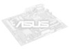
3.
Parallel Printer Connector (25-pin Female)
You can enable the parallel port and choose the IRQ through “Onboard Parallel
Port” in Chipset Features Setup of the BIOS SOFTWARE.
NOTE
: Serial print-
ers must be connected to the serial port.
Parallel (Printer) Port (25-pin Female)
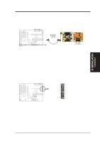
4.
Serial Port COM1 Connectors (One 9-pin Male)
One serial port can be used for pointing devices or other serial devices. See
“Onboard Serial Port” in Chipset Features Setup of the BIOS SOFTWARE.
Serial Port COM 1 (9-pin Male)
5.
Monitor (VGA) Output Connector (One 15-pin Female)
This connector is for a VGA-compatible device.
VGA Port (15-pin Female)