Asus P3-PH5 P3-PH5 User's Manual for English Edtion - Page 32
Uninstalling the optical drive
 |
View all Asus P3-PH5 manuals
Add to My Manuals
Save this manual to your list of manuals |
Page 32 highlights
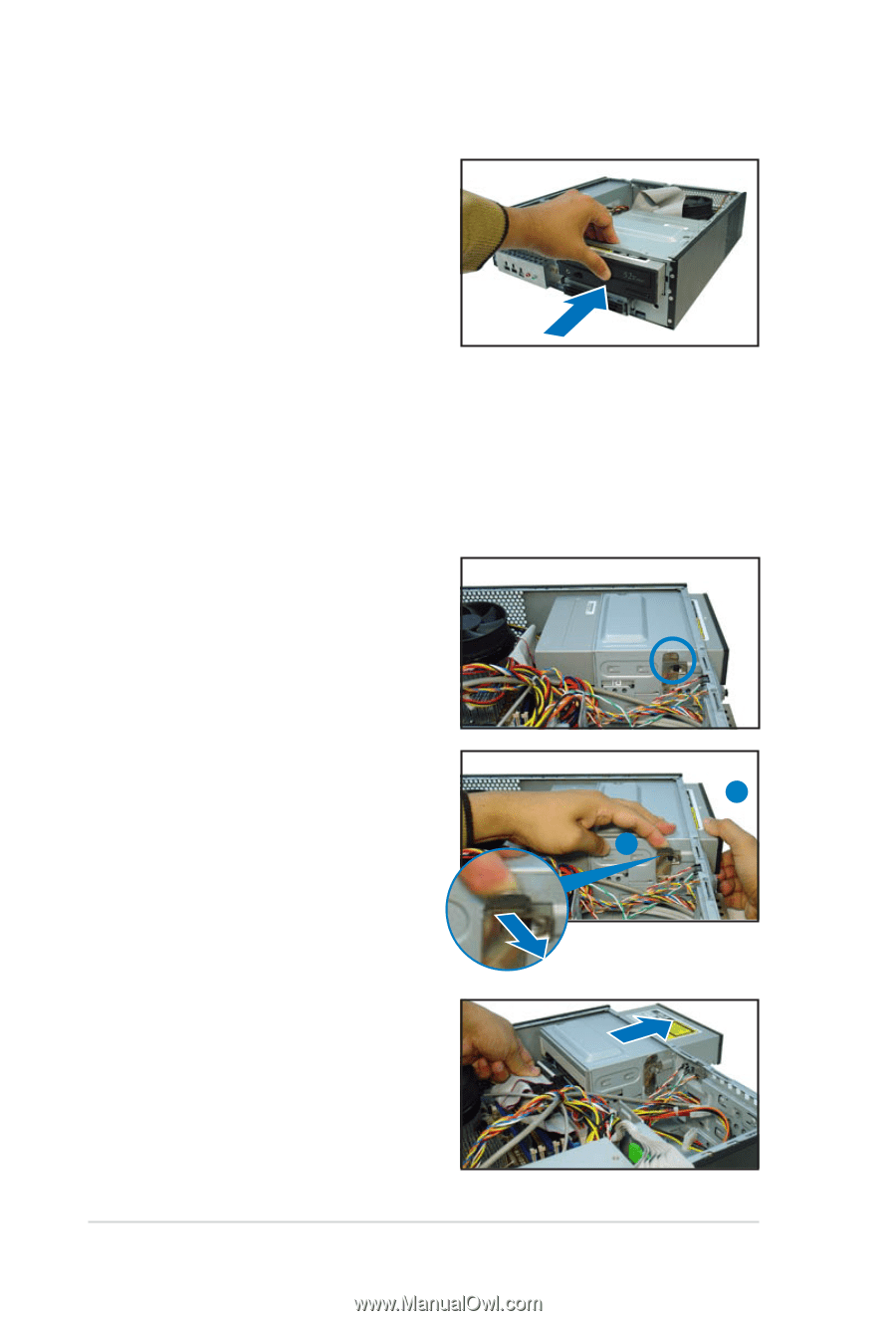
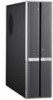
7. Carefully push the optical drive all the way into the bay until the optical drive lock clicks. 8. Connect a 4-pin power plug from the power supply unit to the power connector at the back of the drive. Uninstalling the optical drive In the future, you may have to upgrade or replace a defective optical drive. To uninstall the optical drive: 1. Remove the front panel assembly following the instructions in section "2.3.2 Removing the front panel assembly". 2. Locate the optical drive screw lock. 3. Push the lock to release the optical drive screw (A), then slightly pull the drive out from the bay (B). B A 4. Disconnect the IDE, audio, and power cables and plugs from the back of the drive. 5. Pull out the drive completely from the bay, then replace it following the instructions in the previous section. 2-16 Chapter 2: Basic installation
-
 1
1 -
2
-
3
-
4
-
5
-
6
-
7
-
8
-
9
-
10
-
11
-
12
-
13
-
14
-
15
-
16
-
17
-
18
-
19
-
20
-
21
-
22
-
23
-
24
-
25
-
26
-
 27
27 -
 28
28 -
 29
29 -
 30
30 -
 31
31 -
 32
32 -
 33
33 -
 34
34 -
 35
35 -
 36
36 -
 37
37 -
38
-
39
-
40
-
41
-
42
-
43
-
44
-
45
-
46
-
47
-
48
-
49
-
50
-
51
-
52
-
53
-
54
-
55
-
56
-
57
-
58
-
59
-
60
-
61
-
62
-
63
-
64
-
65
-
66
-
67
-
68
-
69
-
70
-
71
-
72
-
73
-
74
-
75
-
76
-
77
-
78
-
79
-
80
-
81
-
82
-
83
-
84
-
85
-
86
-
87
-
88
-
89
-
90
-
91
-
92
-
93
-
94
-
95
-
96
-
97
-
98
-
99
-
100
 |
 |