Asus P4B P4B User Manual - Page 24
Motherboard layout
 |
View all Asus P4B manuals
Add to My Manuals
Save this manual to your list of manuals |
Page 24 highlights
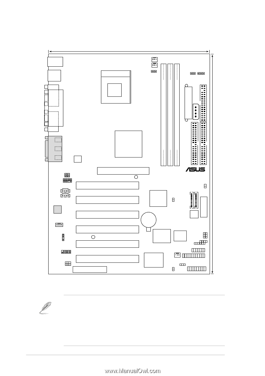
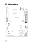
2.2 Motherboard layout PS/2KBMS T: Mouse B: Keyboard USB1 USB2 COM1 22cm (8.7in) Socket 478 PWR_FAN CPU_FAN OVER_VOLT SDRVOL USBPWR1 ATX Power Connector AUX+12V FLOPPY DIMM Socket 1 (64/72-bit, 168-pin module) DIMM Socket 2 (64/72-bit, 168-pin module) DIMM Socket 3 (64/72-bit, 168-pin module) PARALLEL PORT PRIMARY IDE 30.5cm (12.0in) COM2 GAME_AUDIO Line Out Line In Mic In MICF SPEAKER ATX12V Intel 845 Memory Controller Hub (MCH) SECONDARY IDE Accelerated Graphics Port (AGP+1.5V) WARNING 01 23 45 ® P4B AAPANEL CD1 AUX Audio Codec MODEM SPDIFOUT USB2 FUSB AUD_EN1 PCI1 PCI2 PCI3 PCI4 LED1 PCI5 PCI6 CNR Intel I/O Controller Hub (ICH2) TRPWR MS SD CLRCMOS SWITCH CR2032 3V Lithium Cell CMOS Power SMART Super I/O JEN 2Mbit Firmware Hub SPEECH CHASSIS SMB SMARTCON ASUS ASIC with Hardware Monitor CHA_FAN AFPANEL KBPWR HDLED PANEL Figure 2-2 Motherboard Layout The audio CODEC, external GAME/AUDIO connectors, internal audio connectors are optional components, and present in audio models only. The components are grayed in the above motherboard layout. For System Integrators: The SD and MS connectors may or may not be mounted depending on required specifications. 2-2 Chapter 2: Hardware information
-
 1
1 -
2
-
3
-
4
-
5
-
6
-
7
-
8
-
9
-
10
-
11
-
12
-
13
-
14
-
15
-
16
-
17
-
18
-
 19
19 -
 20
20 -
 21
21 -
 22
22 -
 23
23 -
 24
24 -
 25
25 -
 26
26 -
 27
27 -
 28
28 -
 29
29 -
30
-
31
-
32
-
33
-
34
-
35
-
36
-
37
-
38
-
39
-
40
-
41
-
42
-
43
-
44
-
45
-
46
-
47
-
48
-
49
-
50
-
51
-
52
-
53
-
54
-
55
-
56
-
57
-
58
-
59
-
60
-
61
-
62
-
63
-
64
-
65
-
66
-
67
-
68
-
69
-
70
-
71
-
72
-
73
-
74
-
75
-
76
-
77
-
78
-
79
-
80
-
81
-
82
-
83
-
84
-
85
-
86
-
87
-
88
-
89
-
90
-
91
-
92
-
93
-
94
-
95
-
96
-
97
-
98
-
99
-
100
-
101
-
102
-
103
-
104
-
105
-
106
-
107
-
108
-
109
-
110
-
111
-
112
-
113
-
114
-
115
-
116
-
117
-
118
-
119
-
120
-
121
-
122
-
123
-
124
-
125
-
126
-
127
-
128
 |
 |