Asus P4GD1 P4GD1 English user manual E1675
Asus P4GD1 Manual
 |
View all Asus P4GD1 manuals
Add to My Manuals
Save this manual to your list of manuals |
Asus P4GD1 manual content summary:
- Asus P4GD1 | P4GD1 English user manual E1675 - Page 1
P4GD1 Motherboard - Asus P4GD1 | P4GD1 English user manual E1675 - Page 2
express written permission of ASUSTeK COMPUTER INC. ("ASUS"). Product warranty or service will not be extended if: (1) the ASUS HAS BEEN ADVISED OF THE POSSIBILITY OF SUCH DAMAGES ARISING FROM ANY DEFECT OR ERROR IN THIS MANUAL OR PRODUCT. SPECIFICATIONS AND INFORMATION CONTAINED IN THIS MANUAL - Asus P4GD1 | P4GD1 English user manual E1675 - Page 3
viii About this guide ix Typography x P4GD1 specifications summary xi Chapter 1: Product introduction 1.1 Welcome 1-1 1.2 Package contents 1-1 1.3 Special features 1-2 1.3.1 Product highlights 1-2 1.3.2 ASUS Proactive features 1-4 1.3.3 Innovative ASUS features 1-4 Chapter 2: Hardware - Asus P4GD1 | P4GD1 English user manual E1675 - Page 4
utility 4-3 4.1.4 ASUS CrashFree BIOS 2 utility 4-5 4.1.5 ASUS Update utility 4-7 4.2 BIOS setup program 4-10 4.2.1 BIOS menu screen 4-11 4.2.2 Menu bar 4-11 4.2.3 Navigation keys 4-11 4.2.4 Menu items 4-12 4.2.5 Sub-menu items 4-12 4.2.6 Configuration fields 4-12 4.2.7 Pop-up window 4-12 - Asus P4GD1 | P4GD1 English user manual E1675 - Page 5
Status 4-20 4.4.3 USB Configuration 4-21 4.4.4 CPU Configuration 4-22 4.4.5 Chipset 4-23 4.4.6 support 5.1 Installing an operating system 5-1 5.2 Support CD information 5-1 5.2.1 Running the support CD 5-1 5.2.2 Drivers menu 5-2 5.2.3 Utilities menu 5-3 5.2.4 Manuals menu 5-5 5.2.5 ASUS - Asus P4GD1 | P4GD1 English user manual E1675 - Page 6
Contents 5.3.2 AI NET 2 5-10 Using the Virtual Cable Tester 5-10 5.3.3 Audio configurations 5-11 5.4 RAID configurations 5-16 5.4.1 Installing hard disks 5-17 5.4.2 ITE® 8212F RAID configurations 5-18 5.5 Creating a RAID driver disk 5-24 vi - Asus P4GD1 | P4GD1 English user manual E1675 - Page 7
. This equipment generates, uses and can radiate radio frequency energy and, if not installed and used in accordance with manufacturer's instructions, may cause harmful interference to radio communications. However, there is no guarantee that interference will not occur in a particular installation - Asus P4GD1 | P4GD1 English user manual E1675 - Page 8
signal cables from the motherboard, ensure that all service technician or your retailer. Operation safety • Before installing the motherboard and adding devices on it, carefully read all the manuals screws, and staples away from connectors, slots, sockets and circuitry. • Avoid dust, humidity, and - Asus P4GD1 | P4GD1 English user manual E1675 - Page 9
you need when installing and configuring the motherboard. How this guide is organized This manual contains the following parts: • Chapter 1: Product introduction This chapter describes the features of the motherboard and the new technology it supports. • Chapter 2: Hardware information This chapter - Asus P4GD1 | P4GD1 English user manual E1675 - Page 10
following symbols used throughout this manual. D A N G E R / W A R N I N G : Information to prevent injury to yourself when trying to complete a task. C A U T I O N : Information to prevent damage to the components when trying to complete a task. I M P O R T A N T : Instructions that you MUST follow - Asus P4GD1 | P4GD1 English user manual E1675 - Page 11
P4GD1 specifications summary CPU Socket 478 for Intel® Pentium® 4 / Celeron processors Supports Intel® Hyper-Threading Technology Chipset Northbridge: Intel® 915P Memory Controller Hub (MCH) Southbridge: Intel® ICH6 F r o n t S i d e B u s 800/533/400 MHz Memory Dual-channel memory - Asus P4GD1 | P4GD1 English user manual E1675 - Page 12
P4GD1 specifications summary BIOS features Rear panel Internal connectors Power Requirement Form Factor Support CD contents 4 MB Flash ROM, AMI BIOS, PnP, DMI2.0, SM BIOS 2.3, WfM2.0 1 x Parallel port 1 x LAN (RJ-45) port 1 x Rear speaker out port 1 x Side speaker out port 1 x Line In port 1 x - Asus P4GD1 | P4GD1 English user manual E1675 - Page 13
This chapter describes the motherboard features and the new technologies it supports. 1Product introduction - Asus P4GD1 | P4GD1 English user manual E1675 - Page 14
Chapter summary 1.1 Welcome 1-1 1.2 Package contents 1-1 1.3 Special features 1-2 ASUS P4GD1 - Asus P4GD1 | P4GD1 English user manual E1675 - Page 15
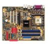
buying an ASUS® P4GD1 motherboard! The motherboard delivers a host of new features and latest technologies, making it another standout in the long line of ASUS quality motherboards! Before you start installing the motherboard s ASUS motherboard support CD D o c u m e n t a t i o n User guide If - Asus P4GD1 | P4GD1 English user manual E1675 - Page 16
allows 6.4GB/s, 4.3GB/s and 3.2GB/s data transfer rates, respectively. The motherboard also supports Intel® Pentium® 4 processors with Hyper-Threading Technology. Intel® 915P The Intel® 915P chipset provides the interface for a processor in the 478-pin package with 400/533/800MHz front side bus (FSB - Asus P4GD1 | P4GD1 English user manual E1675 - Page 17
connectivity to powerful audio and speaker systems. See page 2-23 for details. USB 2.0 technology The motherboard implements the Universal Serial Bus (USB) 2.0 specification, dramatically increasing the voltage levels to ensure stable supply of current for critical components. ASUS P4GD1 1-3 - Asus P4GD1 | P4GD1 English user manual E1675 - Page 18
you to restore the original BIOS data from the support CD in case when the BIOS codes and data are corrupted. This protection eliminates the need to buy a replacement ROM chip. See details on page 4-5. ASUS Q-Fan technology The ASUS Q-Fan technology smartly adjusts the CPU fan speed according to the - Asus P4GD1 | P4GD1 English user manual E1675 - Page 19
This chapter lists the hardware setup procedures that you have to perform when installing system components. It includes description of the jumpers and connectors on the motherboard. 2 Hardware information - Asus P4GD1 | P4GD1 English user manual E1675 - Page 20
Chapter summary 2.1 Before you proceed 2-1 2.2 Motherboard overview 2-2 2.3 Central Processing Unit (CPU 2-6 2.4 System memory 2-12 2.5 Expansion slots 2-16 2.6 Jumpers 2-19 2.7 Connectors 2-22 ASUS P4GD1 - Asus P4GD1 | P4GD1 English user manual E1675 - Page 21
motherboard components or change any motherboard settings. • Unplug the power cord from the wall socket the motherboard, peripherals, and/or components. Onboard LED The motherboard comes motherboard component. The illustration below shows the location of the onboard LED. P4GD1 P4GD1 Onboard LED - Asus P4GD1 | P4GD1 English user manual E1675 - Page 22
or removing the motherboard. Failure to do so can cause you physical injury and damage motherboard components. 2.2.1 Placement direction When installing the motherboard, make sure indicated by circles to secure the motherboard to the chassis. Do not overtighten the screws! Doing so can damage the - Asus P4GD1 | P4GD1 English user manual E1675 - Page 23
30.5cm (12.0in) 2.2.3 Motherboard layout PS/2KBMS T: Mouse B: Keyboard SPDIF_O KBPWR 24.5cm (9.6in) Socket 478 Super I/O DDR DIMM_B2 (64 bit,240-pin module) DDR DIMM_B1 (64 bit,240-pin module) DDR DIMM_A1 (64 bit,240-pin module) DDR DIMM_A2 (64 - Asus P4GD1 | P4GD1 English user manual E1675 - Page 24
2.2.4 Layout Contents Slots 1. DDR DIMM slots 2. PCI slots 3. PCI Express slot Page 2-12 2-18 2-18 Jumpers 1. Clear RTC RAM (3-pin CLRTC1) 2. USB Device wake-up (3-pin USBPW12, USBPW34, USBPW56, USBPW78) 3. Keyboard power (3-pin KBPWR1) Page 2-19 2-20 2-21 Rear panel connectors 1. PS/2 mouse - Asus P4GD1 | P4GD1 English user manual E1675 - Page 25
ATA connectors (7-pin SATA1, SATA2, SATA3, SATA4) 6. CPU fan connector (3-pin CPU_FAN) 7. Power fan connector (3-pin PWR_FAN GAME) 15. Chassis intrusion connector (4-1 pin CHASSIS) 16. Front panel audio connector (10-1 pin AAFP) 17. System panel connectors (20-1 pin 2-31 2-31 2-32 ASUS P4GD1 2-5 - Asus P4GD1 | P4GD1 English user manual E1675 - Page 26
Processing Unit (CPU) 2.3.1 Overview The motherboard comes with a surface mount 478-pin Zero Insertion Force (ZIF) socket designed for the Intel® Pentium® 4 Processor. Take note of the marked corner (with gold triangle) on the CPU. This mark should match a specific corner on the socket to ensure - Asus P4GD1 | P4GD1 English user manual E1675 - Page 27
only if you installed a CPU that supports Hyper-Threading Techonology. 3. Reboot the computer. 2.3.2 Installing the CPU Follow these steps to install a CPU. 1. Locate the 478-pin ZIF socket on the motherboard. P4GD1 P4GD1 478-pin CPU Socket 2. Unlock the socket by pressing the lever sideways - Asus P4GD1 | P4GD1 English user manual E1675 - Page 28
damaging the CPU! 5. When the CPU is in place, push down the socket lever to secure the CPU. The lever clicks on the side tab to indicate that it is locked. After installation, make sure to plug the 4-pin ATX power cable to the motherboard. This motherboard does not support unlocked Intel® Pentium - Asus P4GD1 | P4GD1 English user manual E1675 - Page 29
assembly to ensure optimum thermal condition and performance. • When you buy a boxed Intel® Pentium® 4 processor, the package includes the heatsink, fan, and retention mechanism. • If you buy a CPU separately, make sure that you use only Intel®-certified heatsink and fan. If you purchased a separate - Asus P4GD1 | P4GD1 English user manual E1675 - Page 30
2. Position the fan with the retention mechanism on top of the heatsink. Align and snap the four hooks of the retention mechanism to the holes on each corner of the module base. Make sure that the fan and retention mechanism assembly perfectly fits the heatsink and module base; otherwise, you cannot - Asus P4GD1 | P4GD1 English user manual E1675 - Page 31
+12V GND 4. When the fan and heatsink assembly is in place, connect the CPU fan cable to the connector on the motherboard labeled CPU_FAN. CPU_FAN P4GD1 P4GD1 CPU Fan connector Do not forget to connect the CPU fan connector! Hardware monitoring errors can occur if you fail to plug this connector - Asus P4GD1 | P4GD1 English user manual E1675 - Page 32
motherboard comes with four 184-pin Double Data Rate (DDR) Dual Inline Memory Modules (DIMM) sockets. The following figure illustrates the location of the sockets: DIMM_A1 DIMM_A2 DIMM_B1 DIMM_B2 P4GD1 P4GD1 184-Pin DDR DIMM Sockets x16 modules are not supported in this motherboard. • Due to - Asus P4GD1 | P4GD1 English user manual E1675 - Page 33
sockets • install identical DIMM pair in DIMM_A1 and DIMM_B1 (blue sockets) and identical DIMM pair in DIMM_A2 and DIMM_B2 (black sockets) • install same size DIMMs in DIMM_A1 and DIMM_B1 (blue sockets DDR 32M8 DS GLIL DDR 32M8 DIMM support A* B*C* (Continued on the next page) ASUS P4GD1 2-13 - Asus P4GD1 | P4GD1 English user manual E1675 - Page 34
black slots as one pair of Dual-channel memory configuration. C - support for 4 modules inserted into the yellow and black slots as two pairs of Dual-channel memory configuration. Visit the ASUS website (www.asus.com) for the latest Qualified Vendors List. 2-14 Chapter 2: Hardware information - Asus P4GD1 | P4GD1 English user manual E1675 - Page 35
a DIMM. 2 1. Simultaneously press the retaining clips outward to unlock the DIMM. 1 1 DDR DIMM notch Support the DIMM lightly with your fingers when pressing the retaining clips. The DIMM might get damaged when it flips out with extra force. 2. Remove the DIMM from the socket. ASUS P4GD1 2-15 - Asus P4GD1 | P4GD1 English user manual E1675 - Page 36
the expansion cards that they support. Make sure to unplug the physical injury and damage motherboard components. 2.5.1 Installing Remove the system unit cover (if your motherboard is already installed in a chassis). 3. the necessary BIOS settings, if any. See Chapter 4 for information on BIOS setup. - Asus P4GD1 | P4GD1 English user manual E1675 - Page 37
Data Processor Primary IDE Channel Secondary IDE Channel * These IRQs are usually available for ISA or PCI devices. IRQ assignments for this motherboard - - When using PCI cards on shared slots, ensure that the drivers support "Share IRQ" or that the cards do not need IRQ assignments. Otherwise - Asus P4GD1 | P4GD1 English user manual E1675 - Page 38
a graphics card installed on the PCI Express x16 slot. 2.5.6 PCI Express x1 slot This motherboard supports PCI Express x1 network cards, SCSI cards and other cards that comply with the PCI Express specifications. The figure shows a network card installed on the PCI Express x1 slot. 2-18 Chapter - Asus P4GD1 | P4GD1 English user manual E1675 - Page 39
Clear CMOS You do not need to clear the RTC when the system hangs due to overclocking. For system failure due to overclocking, use the C.P.R. (CPU Parameter Recall) feature. Shut down and reboot the system so the BIOS can automatically reset parameter settings to default values. ASUS P4GD1 2-19 - Asus P4GD1 | P4GD1 English user manual E1675 - Page 40
+5VSB to wake up from S3 and S4 sleep modes (no power to CPU, DRAM in slow refresh, power supply in reduced power mode). The USBPWR12 jumper is for the internal USB connectors that you can connect to additional USB ports. P4GD1 P4GD1 USB device wake-up USBPW12 USBPW34 2 1 +5V (Default) 3 2 +5VSB - Asus P4GD1 | P4GD1 English user manual E1675 - Page 41
the Space Bar). This feature requires an ATX power supply that can supply at least 1A on the +5VSB lead, and a corresponding setting in the BIOS. KBPWR 12 23 +5V +5VSB (Default) P4GD1 P4GD1 Keyboard power setting ASUS P4GD1 2-21 - Asus P4GD1 | P4GD1 English user manual E1675 - Page 42
b l a c k ) . This port connects the side speakers in an 8-channel audio configuration. 6 . L i n e I n p o r t ( l i g h t b l u e ) . This port connects a tape, CD, DVD player, or other audio sources. 7 . L i n e O u t p o r t ( l i m e ) . This port connects a headphone or a speaker. In 4-channel - Asus P4GD1 | P4GD1 English user manual E1675 - Page 43
2 . S e r i a l c o n n e c t o r . This 9-pin COM1 port is for serial devices. 1 3 . S / P D I F O u t p o r t . This port connects an external audio output device via a coaxial S/PDIF cable. 1 4 . P S / 2 k e y b o a r d p o r t ( p u r p l e ) . This port is for a PS/2 keyboard. ASUS P4GD1 2-23 - Asus P4GD1 | P4GD1 English user manual E1675 - Page 44
PIN 1 P4GD1 Floppy disk drive connector 2 . Primary IDE connector (40-1 pin PRI_IDE) This connector is for an Ultra DMA 100/66 signal cable. The Ultra DMA 100/66 signal cable has three connectors: a blue connector for the primary IDE connector on the motherboard, a black connector for an Ultra - Asus P4GD1 | P4GD1 English user manual E1675 - Page 45
100/66 signal cables. These connectors support up to four IDE hard disk o n t r o l l e r item in the BIOS to RAID Mode. See section "4.4.6 Onboard Devices Configuration" for details cable to PIN 1. P4GD1 P4GD1 RAID connectors PRI_RAID • The ITE® 8212F controller supports a maximum of 2 Ultra ATA - Asus P4GD1 | P4GD1 English user manual E1675 - Page 46
RSATA_RXP3 RSATA_RXN3 GND Important notes on Serial ATA • Install the Windows® 2000 Service Pack 4 or the Windows® XP Service Pack1 before using Serial ATA. • Plug your Serial ATA boot disk on the master port (SATA1 and SATA2) to support S3 function. Refer to the table below for details. Serial - Asus P4GD1 | P4GD1 English user manual E1675 - Page 47
CPU, Chassis, and Power fan connectors (3-pin CPU_FAN, 3-pin PWR_FAN, 3-pin CHA_FAN) The fan connectors support cooling fans of 350mA~740mA (8.88W max.) or a total of 1A~2.22A (26.64W max.) at +12V. Connect the fan cables to the fan connectors on the motherboard the motherboard components. These - Asus P4GD1 | P4GD1 English user manual E1675 - Page 48
at the back of the system chassis. These USB connectors comply with USB 2.0 specification that supports up to 480 Mbps connection speed. USB+5V USB_P8USB_P8+ GND NC USB+5V USB_P6USB_P6+ GND NC P4GD1 P4GD1 USB 2.0 connectors USB56 1 USB78 1 USB+5V USB_P7USB_P7+ GND USB+5V USB_P5USB_P5+ GND - Asus P4GD1 | P4GD1 English user manual E1675 - Page 49
ATX 12 V Specification 2.0-compliant PSU passed the motherboard power requirement test with the following configuration: CPU : Memory : intend to install additional devices. ATX12V +12V DC GND +12V DC GND P4GD1 P4GD1 ATX power connectors EATXPWR +3 Volts +12 Volts +12 Volts +5V Standby - Asus P4GD1 | P4GD1 English user manual E1675 - Page 50
(4-pin CD) This connector is for the 4-pin audio cable that connects to the audio connector at the back of the optical drive. Right Audio Channel Ground Ground Left Audio Channel P4GD1 CD P4GD1 CD audio connector 10. GAME/MIDI port connector (16-1 pin GAME) This connector is for a GAME - Asus P4GD1 | P4GD1 English user manual E1675 - Page 51
SENSE1_RETUR SENSE2_RETUR MIC2 MICPWR Line out_R NC Line out_L PORT1 L PORT1 R PORT2 R SENSE_SEND PORT2 L P4GD1 P4GD1 Analog front panel connector Connect a high-definiton front panel audio module to this connector to avail the high-definition audio features of the motherboard. ASUS P4GD1 2-31 - Asus P4GD1 | P4GD1 English user manual E1675 - Page 52
supports several chassis-mounted functions. PLED SPEAKER PLED+ PLED+5V Ground Ground Speaker PANEL IDE_LED+ IDE_LED- PWR Ground Reset Ground P4GD1 P4GD1 or puts the system in SLEEP or SOFT-OFF mode depending on the BIOS settings. Pressing the power switch for more than four seconds while the - Asus P4GD1 | P4GD1 English user manual E1675 - Page 53
This chapter describes the power up Powerin3g up sequence, the vocal POST messages, and ways of shutting down the system. - Asus P4GD1 | P4GD1 English user manual E1675 - Page 54
Chapter summary 3.1 Starting up for the first time 3-1 3.2 Powering off the computer 3-2 ASUS P4GD1 - Asus P4GD1 | P4GD1 English user manual E1675 - Page 55
then runs the power-on self tests or POST. While the tests are running, the BIOS beeps (see BIOS beep codes table below) or additional messages appear on the screen. If you do not see on, hold down the key to enter the BIOS Setup. Follow the instructions in Chapter 4. ASUS P4GD1 3-1 - Asus P4GD1 | P4GD1 English user manual E1675 - Page 56
u r n O f f button to shut down the computer. 3. The power supply should turn off after Windows® shuts down. 3.2.2 Using the dual function power switch While the system is ON, pressing the power switch for -off mode, depending on the BIOS setting. Pressing the power switch for more than four seconds - Asus P4GD1 | P4GD1 English user manual E1675 - Page 57
This chapter tells how to change the system settings through the BIOS Setup menus. Detailed descriptions of the BIOS parameters are also provided. 4 BIOS setup - Asus P4GD1 | P4GD1 English user manual E1675 - Page 58
Chapter summary 4.1 Managing and updating your BIOS 4-1 4.2 BIOS setup program 4-10 4.3 Main menu 4-13 4.4 Advanced menu 4-17 4.5 Power menu 4-28 4.6 Boot menu 4-33 4.7 Exit menu 4-37 ASUS P4GD1 - Asus P4GD1 | P4GD1 English user manual E1675 - Page 59
a floppy disk during POST.) 3. A S U S C r a s h F r e e B I O S 2 (Updates the BIOS using a bootable floppy disk or the motherboard support CD when the BIOS file fails or gets corrupted.) 4. A S U S U p d a t e (Updates the BIOS in Windows® environment.) Refer to the corresponding sections for - Asus P4GD1 | P4GD1 English user manual E1675 - Page 60
during the Power-On Self Tests (POST). To update the BIOS using EZ Flash: 1. Visit the ASUS website (www.asus.com) to download the latest BIOS file for the motherboard and rename the same to P 4 G D 1 . R O M. 2. Save the BIOS file to a floppy disk, then restart the system. 3. Press + - Asus P4GD1 | P4GD1 English user manual E1675 - Page 61
BIOS screens are for reference only. The actual BIOS screen displays may not be exactly the same as shown. 1. Copy the AFUDOS utility (afudos.exe) from the motherboard support Extension name 3. Press . The utility copies the current BIOS file to the floppy disk. A:\>afudos /oOLDBIOS1.ROM AMI - Asus P4GD1 | P4GD1 English user manual E1675 - Page 62
(www.asus.com) and download the latest BIOS file for the motherboard. Save the BIOS file to a bootable floppy disk. Write the BIOS filename on a piece of paper. You need to type the exact BIOS filename at the DOS prompt. 2. Copy the AFUDOS utility (afudos.exe) from the motherboard support CD to - Asus P4GD1 | P4GD1 English user manual E1675 - Page 63
2 utility The ASUS CrashFree BIOS 2 is an auto recovery tool that allows you to restore the BIOS file when it fails or gets corrupted during the updating process. You can update a corrupted BIOS file using the motherboard support CD or the floppy disk that contains the updated BIOS file. • Prepare - Asus P4GD1 | P4GD1 English user manual E1675 - Page 64
the BIOS! Doing so can cause system boot failure! 4. Restart the system after the utility completes the updating process. The recovered BIOS may not be the latest BIOS version for this motherboard. Visit the ASUS website (www.asus.com) to download the latest BIOS file. 4-6 Chapter 4: BIOS setup - Asus P4GD1 | P4GD1 English user manual E1675 - Page 65
you to manage, save, and update the motherboard BIOS in Windows® environment. The ASUS Update utility allows you to: • Save the current BIOS file • Download the latest BIOS file from the Internet • Update the BIOS from an updated BIOS file • Update the BIOS directly from the Internet, and • View the - Asus P4GD1 | P4GD1 English user manual E1675 - Page 66
To update the BIOS through the Internet: 1. Launch the ASUS Update utility from the Windows® desktop by clicking S t a r t > P r o g r a m s > A S U S > A S U S U p d a t e > A S U S U p d a t e. The ASUS Update main window appears. 2. Select U p d a t e B I O S f r o m 3. Select the ASUS FTP site - Asus P4GD1 | P4GD1 English user manual E1675 - Page 67
p d a t e. The ASUS Update main window appears. 2. Select U p d a t e B I O S f r o m a f i l e option from the drop-down menu, then click N e x t. 3. Locate the BIOS file from the O p e n window, then click S a v e. 4. Follow the screen instructions to complete the update process. ASUS P4GD1 4-9 - Asus P4GD1 | P4GD1 English user manual E1675 - Page 68
under the Exit Menu. See section "4.7 Exit Menu." • The BIOS setup screens shown in this section are for reference purposes only, and may not exactly match what you see on your screen. • Visit the ASUS website (www.asus.com) to download the latest BIOS file for this motherboard and . 4-10 Chapter - Asus P4GD1 | P4GD1 English user manual E1675 - Page 69
4.2.1 BIOS menu screen Menu items Menu bar Configuration fields General help System Time System Date Legacy Diskette A Language Primary IDE Master Primary IDE keys to select items in the menu and change the settings. Some of the navigation keys differ from one screen to another. ASUS P4GD1 4-11 - Asus P4GD1 | P4GD1 English user manual E1675 - Page 70
highlighted item on the menu bar displays the specific items for that menu. For example, selecting :10:19] [Thu 03/27/2003] [1.44M, 3.5 in] [English] :[ST320413A] :[ASUS CD-S340] :[Not Detected] :[Not Detected] :[Not Detected] :[Not Detected] Use [ENTER window Scroll bar 4-12 Chapter 4: BIOS setup - Asus P4GD1 | P4GD1 English user manual E1675 - Page 71
drive installed. Configuration options: [Disabled] [360K, 5.25 in.] [1.2M , 5.25 in.] [720K , 3.5 in.] [1.44M, 3.5 in.] [2.88M, 3.5 in.] 4.3.4 Language [English] Allows you to choose the BIOS language version from the options. Configuration options: [Français] [German] [English] ASUS P4GD1 4-13 - Asus P4GD1 | P4GD1 English user manual E1675 - Page 72
Supported Type LBA/Large Mode Block(Multi-sector Transfer) PIO Mode DMA Mode Smart Monitoring 32Bit Data Transfer [Auto] [Auto] [Auto] [Auto] [Auto] [Auto] [Disabled] The BIOS appropriate IDE device type. Select CDROM if you are specifically configuring a CD-ROM drive. Select ARMD (ATAPI Removable - Asus P4GD1 | P4GD1 English user manual E1675 - Page 73
to Enhanced Mode if you are using native OS, such as Windows® 2000/XP. Configuration options: [Disabled] [Compatible Mode] [Enhanced Mode] Enhanced Mode Support On [S-ATA] The default setting S-ATA allows you to use ATA ports o n l y i f you did not install any Serial ATA device. ASUS P4GD1 4-15 - Asus P4GD1 | P4GD1 English user manual E1675 - Page 74
set to any of these options and encounter problems, revert to the default setting S - Processor Type Speed Count : Intel(R) Pentium(R) CPU 3.40GHz : 2800 MHz : 1 System Memory Size : 512MB AMI BIOS Displays the auto-detected BIOS information Processor Displays the auto-detected CPU specification - Asus P4GD1 | P4GD1 English user manual E1675 - Page 75
unstable, return to the default. AI Overclocking [Auto] Allows selection of CPU overclocking options to achieve desired CPU internal frequency. Select either one of the preset overclocking options. Configuration options: [Manual] [Auto] [Standard] [Overclock Profile] [ AI NOS] ASUS P4GD1 4-17 - Asus P4GD1 | P4GD1 English user manual E1675 - Page 76
sets the twin turbo non-delay overclocking system percentage. Configuration options: [Disabled] [Overclock 3%] [Overclock 5%] [Overclock 7%] [Overclock 10%] [Overclock 15%] [Overclock 20%] [Overclock 30%] 4-18 Chapter 4: BIOS setup - Asus P4GD1 | P4GD1 English user manual E1675 - Page 77
the value. Table 4.4.2 FSB/CPU External Frequency Synchronization Front Side Bus FSB 800 FSB 533 FSB 400 CPU External Frequency 200 MHz 133 MHz 100 MHz Selecting a very high CPU frequency may cause the system to become unstable! If this happens, revert to the default setting. ASUS P4GD1 4-19 - Asus P4GD1 | P4GD1 English user manual E1675 - Page 78
MHz] [400 MHz] [600 MHz] Selecting a DRAM frequency that is not supported by your DIMM module may cause the system to become unstable! If this ] Selects the PCI Clock Synchronization mode. Configuration options: [To CPU] [33.33MHz] [Auto] Spread Spectrum [Auto] Enables, ] 4-20 Chapter 4: BIOS setup - Asus P4GD1 | P4GD1 English user manual E1675 - Page 79
USB controller legacy mode is enabled. If no USB device is detected, the legacy USB support is disabled. Configuration options: [Disabled] [Enabled] [Auto] USB 2.0 Controller [Enabled] Allows to HiSpeed (480 Mbps) or FullSpeed (12 Mbps). Configuration options: [FullSpeed] [HiSpeed] ASUS P4GD1 4-21 - Asus P4GD1 | P4GD1 English user manual E1675 - Page 80
you to set the VID CMOS setting at which the processor is to run. The default value of this item is auto-detected by BIOS. Use the < + > or keys to set to [Auto], the BIOS will automatically check the CPU's capability to enable the C1E support. In C1E mode, the CPU power consumption is lower when - Asus P4GD1 | P4GD1 English user manual E1675 - Page 81
CPU internal thermal control. Configuration options: [Disabled] [Auto] Hyper-Threading Technology [Enabled] Allows you to enable or disable the processor SPD (Serial Presence Detect). When disabled, you can manually set the DRAM timing parameters through the DRAM sub- ] [5 Clocks] ASUS P4GD1 4-23 - Asus P4GD1 | P4GD1 English user manual E1675 - Page 82
Graphics root control. Configuration options: [Auto] [Disabled] [Enabled] Slot Power [Auto] Sets the slot operating power. Configuration options: [Auto] [Light] [Normal] [Heavy] [Heavier] 4-24 Chapter 4: BIOS setup - Asus P4GD1 | P4GD1 English user manual E1675 - Page 83
[IRQ7] [Disabled] Onboard High Definition Codec [Enabled] Enables or disables the onboard High-Definition Audio CODEC. Configuration options: [Enabled] [Disabled] OnBoard PCIEX GbE LAN [Enabled] Allows you to . Configuration options: [Disabled] [3F8/IRQ4] [3E8/IRQ4] [2E8/IRQ3] ASUS P4GD1 4-25 - Asus P4GD1 | P4GD1 English user manual E1675 - Page 84
: [Disabled] [200/300] [200/330] [208/300] [208/330] MIDI IRQ Select [IRQ10] Sets MIDI port IRQ address. Configuration options: [IRQ5] [IRQ10] [IRQ11] 4-26 Chapter 4: BIOS setup - Asus P4GD1 | P4GD1 English user manual E1675 - Page 85
Option F1 General Help F10 Save and Exit ESC Exit Plug And Play O/S [No] When set to [No], BIOS configures all the devices in the system. When set to [Yes] and if you install a Plug and Play operating the latter can function correctly. Configuration options: [Disabled] [Enabled] ASUS P4GD1 4-27 - Asus P4GD1 | P4GD1 English user manual E1675 - Page 86
2.0 Support ACPI APIC Support APM Configuration Hardware Monitor [Auto] [No] [No] [Enabled] Configure CPU. BIOS POST on S3/STR resume. Configuration options: [Yes] [No] 4.5.3 ACPI 2.0 Support [No] Allows you to add more tables for Advanced Configuration and Power Interface (ACPI) 2.0 specifications - Asus P4GD1 | P4GD1 English user manual E1675 - Page 87
try. Turning an external modem off and then back on while the computer is off causes an initialization string that turns the system power on. ASUS P4GD1 4-29 - Asus P4GD1 | P4GD1 English user manual E1675 - Page 88
lead. Configuration options: [Disabled] [Enabled] Power On By PS/2 Keyboard [Disabled] Allows you to use specific keys on the keyboard to turn on the system. This feature requires an ATX power supply that provides at +5VSB lead. Configuration options: [Disabled] [Enabled] 4-30 Chapter 4: BIOS setup - Asus P4GD1 | P4GD1 English user manual E1675 - Page 89
speed in rotations per minute (RPM). If the fan is not connected to the motherboard, the field shows N/A. CPU Q-Fan Control [Disabled] Allows you to enable or disable the ASUS Q-Fan feature that smartly adjusts the fan speeds for more efficient system operation. When this field is set to [Enabled - Asus P4GD1 | P4GD1 English user manual E1675 - Page 90
Intel®'s PWM fan specification. When using this type of CPU fan, you can not reduce the CPU fan speed even if you set the CPU Q-Fan Mode to [PWM]. CPU Fan Ratio [Auto] Allows you to select the appropriate CPU the chassis, the specific field shows N/A. fan connector, the specific field shows N/A. VCORE - Asus P4GD1 | P4GD1 English user manual E1675 - Page 91
Priority 1st Boot Device 2nd Boot Device 3rd Boot Device [1st FLOPPY DRIVE] [PM-ST330620A] [PS-ASUS CD-S360] 1st ~ xxth Boot Device [1st Floppy Drive] These items specify the boot device priority devices installed in the system. Configuration options: [xxxxx Drive] [Disabled] ASUS P4GD1 4-33 - Asus P4GD1 | P4GD1 English user manual E1675 - Page 92
Support Wait For 'F1' If Error Hit 'DEL' Message Display Interrupt 19 Capture [Enabled] [Enabled] [Force BIOS] [On] [Auto] [Enabled] [Enabled] [Disabled] Allows BIOS ASUS MyLogo™ feature. Add On ROM Display Mode [Force BIOS] Sets the display mode for option ROM. Configuration options: [Force BIOS] - Asus P4GD1 | P4GD1 English user manual E1675 - Page 93
same steps as in setting a user password. To clear the supervisor password, select the Change Supervisor Password then press . The message "Password Uninstalled" appears. ASUS P4GD1 4-35 - Asus P4GD1 | P4GD1 English user manual E1675 - Page 94
If you forget your BIOS password, you can clear clear it by erasing the CMOS Real Time Clock (RTC) RAM. See section "2.6 Jumpers" for information on type a password composed of at least six letters and/or numbers, then press . 3. Confirm the password when prompted. 4-36 Chapter 4: BIOS setup - Asus P4GD1 | P4GD1 English user manual E1675 - Page 95
menu items allow you to load the optimal or failsafe default values for the BIOS items, and save or discard your changes to the BIOS items. Exit Options Exit & Save Changes Exit & Discard Changes Discard Changes Load the options from this menu or from the legend bar to exit. ASUS P4GD1 4-37 - Asus P4GD1 | P4GD1 English user manual E1675 - Page 96
when the PC is turned off. When you select this option, a confirmation window appears. Select Y e s to save changes and exit. If you attempt to to fields other than System Date, System Time, and Password, the BIOS asks for a confirmation before exiting. Discard Changes This option allows you - Asus P4GD1 | P4GD1 English user manual E1675 - Page 97
This chapter describes the contents of the support CD that comes with the motherboard package. 5 Software support - Asus P4GD1 | P4GD1 English user manual E1675 - Page 98
Chapter summary 5.1 Installing an operating system 5-1 5.2 Support CD information 5-1 5.3 Software information 5-8 5.4 RAID configurations 5-16 5.5 Creating a RAID driver disk 5-24 ASUS P4GD1 - Asus P4GD1 | P4GD1 English user manual E1675 - Page 99
that you install Windows® 2000 Service Pack 4 or the Windows® XP Service Pack 1 or later versions before installing the drivers for better compatibility and system stability. 5.2 Support CD information The support CD that came with the motherboard package contains the drivers, software applications - Asus P4GD1 | P4GD1 English user manual E1675 - Page 100
QFE Update Installs the Quick Fix Engineering (QFE) driver updates. Intel Chipset Inf Update Program This item installs the Intel® Chipset INF Update Program. This driver enables Plug-n-Play INF support for the Intel® chipset components on the motherboard. When installed to the target system, this - Asus P4GD1 | P4GD1 English user manual E1675 - Page 101
RAID setup. USB 2.0 Driver Installs the USB 2.0 driver. The screen display and drivers option may not be the same for different operating system versions. 5.2.3 Utilities menu The Utilities menu shows the applications and other software that the motherboard supports. Marvell Yukon VCT Application - Asus P4GD1 | P4GD1 English user manual E1675 - Page 102
the motherboard BIOS in a Windows® environment. This utility requires an Internet connection either through a network or an Internet Service Provider (ISP). See page 4-7 for details. ASUS Ai Booster The ASUS AI Booster application allows you to overclock the CPU speed in a Windows® environment - Asus P4GD1 | P4GD1 English user manual E1675 - Page 103
manual. Install the Adobe® Acrobat® Reader from the Utilities menu before opening the manual files. ITE8212 RAID User's Manual Allows you to open the ITE® 8212F RAID User's manual. The screen display and manuals option may not be the same for different operating system versions. ASUS P4GD1 5-5 - Asus P4GD1 | P4GD1 English user manual E1675 - Page 104
front cover of this user guide. 5.2.6 Other information The icons on the top right corner of the screen give additional information on the motherboard and the contents of the support CD. Click an icon to display the specified information. Motherboard Info Displays the general specifications of the - Asus P4GD1 | P4GD1 English user manual E1675 - Page 105
the support CD contents in graphical format. Technical support Form Displays the ASUS Technical Support Request Form that you have to fill out when requesting technical support. Filelist Displays the contents of the support CD and a brief description of each in text format. ASUS P4GD1 5-7 - Asus P4GD1 | P4GD1 English user manual E1675 - Page 106
support CD have wizards that will conveniently guide you through the installation. View the online help or readme file that came with the software application for more information. 5.3.1 ASUS MyLogo™ The ASUS BIOS file, then click N e x t. The ASUS MyLogo window appears. 6. From the left window pane - Asus P4GD1 | P4GD1 English user manual E1675 - Page 107
7. When the logo images appear on the right window pane, select an image to enlarge by clicking on it. 8. Adjust the boot image to your desired size by selecting a value on the R a t i o box. 9. When the screen returns to the ASUS Update utility, flash the original BIOS to load the new boot logo. 10 - Asus P4GD1 | P4GD1 English user manual E1675 - Page 108
on the Virtual Cable Tester™ main window is disabled if no problem is detected on the LAN cable(s) connected to the LAN port(s). • If you want the system to check the LAN cable before entering the OS, enable the P O S T C h e c k L A N c a b l e item in the BIOS. 5-10 Chapter 5: Software support - Asus P4GD1 | P4GD1 English user manual E1675 - Page 109
when you install the Realtek Audio Driver from the motherboard support CD. Refer to section "5.2.2 Driver's Menu". Launching the Realtek Sound Manager From the Windows® taskbar, double-click the button to display the following. Karaoke Environment settings Equalizer settings ASUS P4GD1 5-11 - Asus P4GD1 | P4GD1 English user manual E1675 - Page 110
o k e . The Karaoke section allows you to toggle the voice and adjust the pitch of the audio. Click the up or down arrows to adjust the pitch or the icon to toggle the voice. Speaker setup to display the function of the front and back panel audio ports. 5-12 Chapter 5: Software support - Asus P4GD1 | P4GD1 English user manual E1675 - Page 111
l option displays your audio driver version, DirectX version, audio controller, and audio CODEC. Enable the option button to display the Sound Effect icon on the system tray. To change the language interface, click the combo list box and select from the list of supported languages. ASUS P4GD1 5-13 - Asus P4GD1 | P4GD1 English user manual E1675 - Page 112
Wizard The A u d i o W i z a r d guides you to the proper audio port for the device you plugged in. Click the F r o n t P a n e l or B a c k P a n e l button to display their respective audio ports. Click O K when finished. 5-14 • The front panel audio connectors support both the Realtek® Jack - Asus P4GD1 | P4GD1 English user manual E1675 - Page 113
the rear panel change when you select the 4-channel, 6-channel or 8-channel audio configuration as shown in the following table. Audio 2, 4, 6, or 8-channel configuration Port Light Blue Lime Pink Gray Black Speaker Out Mic In Rear Speaker Out Side Speaker Out Center/Subwoofer ASUS P4GD1 5-15 - Asus P4GD1 | P4GD1 English user manual E1675 - Page 114
configure IDE and Serial ATA hard disk drives as RAID sets. The motherboard supports the following RAID configurations. R A I D 0 (Data striping) disk drive included in a created RAID set, copy first the RAID driver from the support CD to a floppy disk before you install an operating system to the - Asus P4GD1 | P4GD1 English user manual E1675 - Page 115
5.4.1 Installing hard disks The motherboard supports Ultra DMA 133/100/66 and Serial ATA hard disk drives. For optimal performance, install identical drives of the the drive bays. 2. Connect the SATA signal cables. 3. Connect a SATA power cable to the power connector on each drive. ASUS P4GD1 5-17 - Asus P4GD1 | P4GD1 English user manual E1675 - Page 116
ITE® 8212F RAID configurations The ITE® 8212F IDE RAID controller supports RAID 0, RAID 1, RAID 0+1 and JBOD configurations. Use the IT8212 BIOS Setup Utility or the ATA RAID Manager application to configure a disk array. Setting the BIOS RAID items After installing the hard disk drives, make sure - Asus P4GD1 | P4GD1 English user manual E1675 - Page 117
your selection or to exit. Auto-configuring a RAID array This option allows you to select a supported RAID set for the utility to automatically configure. To auto-configure a RAID set: 1. From the IT8212 Setup 3. Press to save your RAID set. 4. Press to exit. ASUS P4GD1 5-19 - Asus P4GD1 | P4GD1 English user manual E1675 - Page 118
Defining a RAID array This option allows you to define supported RAID arrays. To define a RAID array: 1. From the IT8212 Setup Utility screen, press . The following Y Y Y Y ∗ : Capacity (GB) [↑] Up [↓] Down [Space] Change Option [Ctrl-Y] Save [ESC] Exit 5-20 Chapter 5: Software support - Asus P4GD1 | P4GD1 English user manual E1675 - Page 119
[↓] Down ♦ : Bootable Array [D] Delete [ESC] Exit 2. Use the up or down arrow keys to select a RAID array, then press to delete. 3. Press to exit. ASUS P4GD1 5-21 - Asus P4GD1 | P4GD1 English user manual E1675 - Page 120
/D1 Drive Name XXXXXXXXXX XXXXXXXXXX [ Drive List] Size (MB) XXXXX Size (MB) XXXXX XXXXXX ∗ : Capacity (GB) [↑] Up [↓] Down [Enter] Select [ESC] Exit 5-22 Chapter 5: Software support - Asus P4GD1 | P4GD1 English user manual E1675 - Page 121
down arrow keys to select a drive, then press . Follow succeeding screen instructions. 4. Press to exit. Viewing your RAID configuration This option allows you or right keys or the space bar enable or disable the A u t o - r e b u i l d item. 4. Press to exit. ASUS P4GD1 5-23 - Asus P4GD1 | P4GD1 English user manual E1675 - Page 122
disk A floppy disk with the RAID driver is required when installing Windows® 2000/XP operating system on a hard disk drive that is included in a RAID set. To create a RAID driver disk: 1. Place the motherboard support CD into the CD-ROM drive. 2. When the D r i v e r s menu appears, select the
-
 1
1 -
 2
2 -
 3
3 -
 4
4 -
 5
5 -
 6
6 -
 7
7 -
8
-
9
-
10
-
11
-
12
-
13
-
14
-
15
-
16
-
17
-
18
-
19
-
20
-
21
-
22
-
23
-
24
-
25
-
26
-
27
-
28
-
29
-
30
-
31
-
32
-
33
-
34
-
35
-
36
-
37
-
38
-
39
-
40
-
41
-
42
-
43
-
44
-
45
-
46
-
47
-
48
-
49
-
50
-
51
-
52
-
53
-
54
-
55
-
56
-
57
-
58
-
59
-
60
-
61
-
62
-
63
-
64
-
65
-
66
-
67
-
68
-
69
-
70
-
71
-
72
-
73
-
74
-
75
-
76
-
77
-
78
-
79
-
80
-
81
-
82
-
83
-
84
-
85
-
86
-
87
-
88
-
89
-
90
-
91
-
92
-
93
-
94
-
95
-
96
-
97
-
98
-
99
-
100
-
101
-
102
-
103
-
104
-
105
-
106
-
107
-
108
-
109
-
110
-
111
-
112
-
113
-
114
-
115
-
116
-
117
-
118
-
119
-
120
-
121
-
122
 |
 |

Motherboard
P4GD1