Asus P4RD1-MX Motherboard DIY Troubleshooting Guide - Page 35
P4RD1-MX SATA connectors, P4RD1-MX TV out connector
 |
View all Asus P4RD1-MX manuals
Add to My Manuals
Save this manual to your list of manuals |
Page 35 highlights
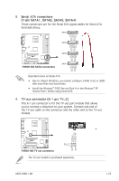
3. Serial ATA connectors (7-pin SATA1, SATA2, SATA3, SATA4) These connectors are for the Serial ATA signal cables for Serial ATA hard disk drives. SATA4 SATA3 GND RSATA_TXP4 RSATA_TXN4 GND RSATA_RXP4 RSATA_RXN4 GND GND RSATA_TXP3 RSATA_TXN3 GND RSATA_RXP3 RSATA_RXN3 GND GND RSATA_TXP2 RSATA_TXN2 GND RSATA_RXP2 RSATA_RXN2 GND P4RD1-MX ® P4RD1-MX SATA connectors SATA2 SATA1 GND RSATA_TXP1 RSATA_TXN1 GND RSATA_RXP1 RSATA_RXN1 GND Important notes on Serial ATA • Due to chipset limitation, you cannot configure a RAID 0 set or JBOD with more than two hard drives. • Install the Windows® 2000 Service Pack 4 or the Windows® XP Service Pack1 before using Serial ATA. 4. TV-out connector (6-1 pin TV_C) This 6-1 pin connector is for the TV-out port module that allows you to connect a television to your system. Connect one end of the TV-out cable to this connector and the other end to the TV-out module. CVBS out S-video C out S-video Y out P4RD1-MX ® P4RD1-MX TV out connector TV_C 1 The TV-out module is purchased separately. ASUS P4RD1-MX GND GND 1-23
-
 1
1 -
2
-
3
-
4
-
5
-
6
-
7
-
8
-
9
-
10
-
11
-
12
-
13
-
14
-
15
-
16
-
17
-
18
-
19
-
20
-
21
-
22
-
23
-
24
-
25
-
26
-
27
-
28
-
29
-
 30
30 -
 31
31 -
 32
32 -
 33
33 -
 34
34 -
 35
35 -
 36
36 -
 37
37 -
 38
38 -
 39
39 -
 40
40 -
41
-
42
-
43
-
44
-
45
-
46
-
47
-
48
-
49
-
50
-
51
-
52
-
53
-
54
-
55
-
56
-
57
-
58
-
59
-
60
-
61
-
62
-
63
-
64
-
65
-
66
-
67
-
68
-
69
-
70
-
71
-
72
-
73
-
74
-
75
-
76
-
77
-
78
-
79
-
80
-
81
-
82
 |
 |
