Asus P4S800-MX SE Motherboard DIY Troubleshooting Guide - Page 24
Chapitre 1 : Introduction au produit - memory
 |
View all Asus P4S800-MX SE manuals
Add to My Manuals
Save this manual to your list of manuals |
Page 24 highlights
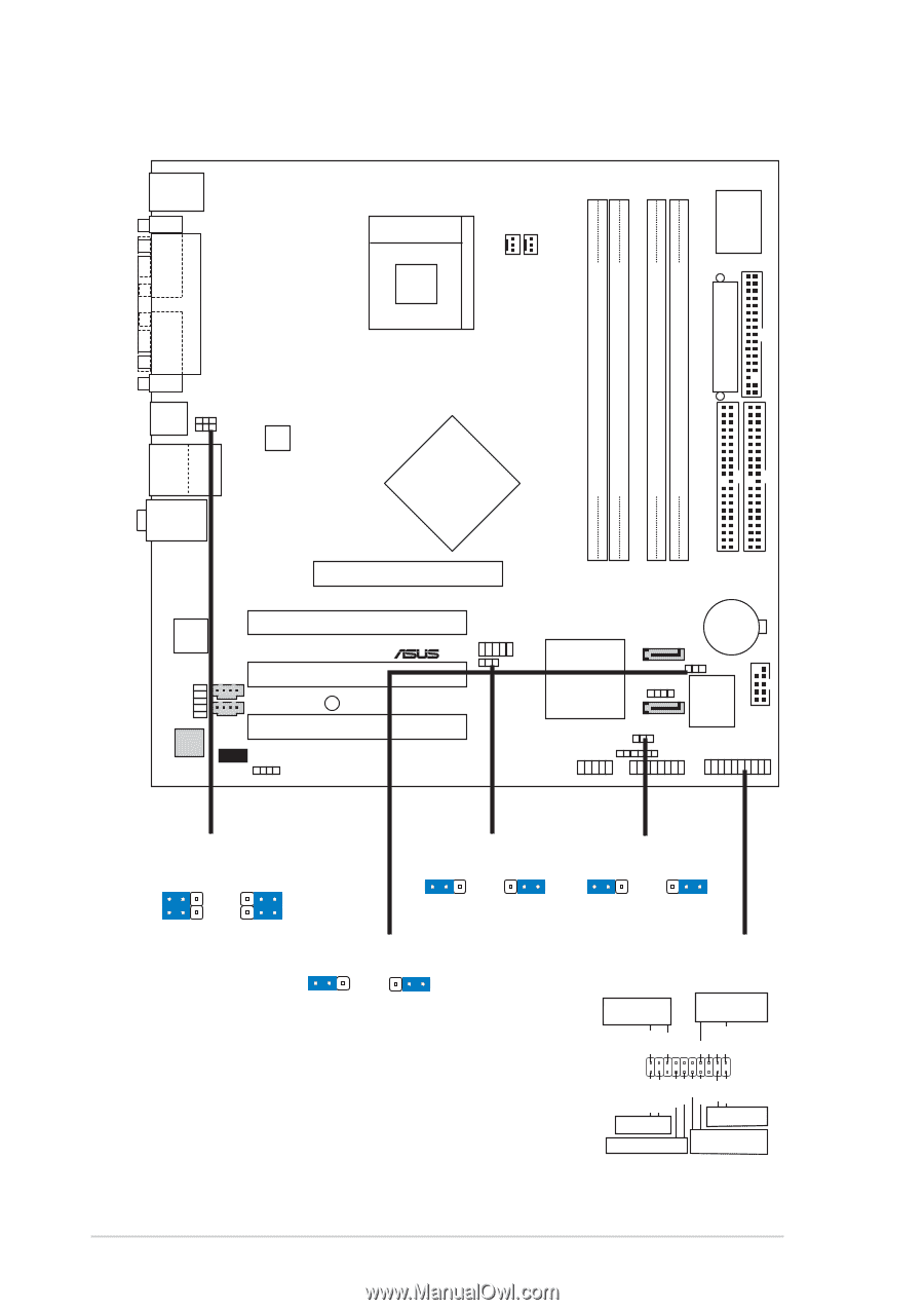
P4P800-VM PS/2KBMS T: Mouse B: Keyboard COM1 Socket 478 Super I/O ATX Power Connector FLOPPY1 DDR DIMM_B1 (64 bit,184-pin module) DDR DIMM_B1 (64 bit,184-pin module) CHA_FAN1 CPU_FAN P4P800-VM DDR DIMM_A1 (64 bit,184-pin module) DDR DIMM_A2 (64 bit,184-pin module) PARALLEL PORT PRI_IDE1 SEC_IDE1 VGA1 USB1 USB2 USBPW12 USBPW34 USB2.0 T: USB3 B: USB4 Top: RJ-45 ATX12V1 Top:Line In Center:Line Out Below:Mic In Intel 865G Memory Controller Hub Accelerated Graphics Port (AGP1) Intel Lan 82562EZ (10/100Nbps) IAPANEL1 CD1 AUX1 AD1980 CODEC MDC1 SPDIF1 PCI1 PCI2 SB_PWR1 PCI3 USB56 ® Intel SATA2 CR2032 3V Lithium Cell CMOS Power USBPW56 ICH5 CLRTC1 4Mbit Firmware Hub (South CHASSIS1 Bridge) SATA1 COM2 USBPW78 SMB1 USB78 GAME1 PANEL1 USBPW12 USBPW34 12 23 +5V (Default) +5VSB USBPW56 12 23 +5V (Default) CLRTC1 12 23 +5VSB Normal (Default) Clear CMOS USBPW78 12 23 +5V (Default) +5VSB PANEL1 Power LED Speaker connector PLED+ PLED+5V Ground Ground Speaker IDE_LED+ IDE_LED- ExtSMI# Ground PWR Ground Reset Ground 1-6 IDE_LED SMI Lead Reset SW ATX Power Switch* *Requiert une alimentation ATX Chapitre 1 : Introduction au produit
-
 1
1 -
2
-
3
-
4
-
5
-
6
-
7
-
8
-
9
-
10
-
11
-
12
-
13
-
14
-
15
-
16
-
17
-
18
-
 19
19 -
 20
20 -
 21
21 -
 22
22 -
 23
23 -
 24
24 -
 25
25 -
 26
26 -
 27
27 -
 28
28 -
 29
29 -
30
-
31
-
32
-
33
-
34
-
35
-
36
-
37
-
38
-
39
-
40
-
41
-
42
-
43
-
44
-
45
-
46
-
47
-
48
-
49
-
50
-
51
-
52
-
53
-
54
-
55
-
56
-
57
-
58
-
59
-
60
-
61
-
62
-
63
-
64
-
65
-
66
-
67
-
68
-
69
-
70
-
71
-
72
-
73
-
74
-
75
-
76
-
77
-
78
-
79
-
80
-
81
-
82
-
83
-
84
-
85
-
86
-
87
-
88
 |
 |