Asus P5G41-M LE/CSM User Manual - Page 41
P5G41-M LE Parallel Port Connector
 |
View all Asus P5G41-M LE/CSM manuals
Add to My Manuals
Save this manual to your list of manuals |
Page 41 highlights
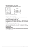
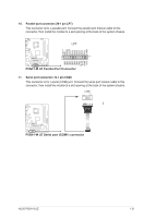
10. Parallel port connector (26-1 pin LPT) This connector is for a parallel port. Connect the parallel port module cable to this connector, then install the module to a slot opening at the back of the system chassis. LPT SLCT PE BUSY ACK# PD7 PD6 PD5 PD4 PD3 PD2 PD1 PD0 STB# P5G41-M LE PIN 1 GND GND GND GND GND GND GND GND SLIN# INIT# ERR# AFD P5G41-M LE Parallel Port Connector 11. Serial port connector (10-1 pin COM) This connector is for a serial (COM) port. Connect the serial port module cable to this connector, then install the module to a slot opening at the back of the system chassis. COM1 PIN 1 P5G41-M LE P5G41-M LE Serial port (COM1) connector ASUS P5G41-M LE 1-31
-
 1
1 -
2
-
3
-
4
-
5
-
6
-
7
-
8
-
9
-
10
-
11
-
12
-
13
-
14
-
15
-
16
-
17
-
18
-
19
-
20
-
21
-
22
-
23
-
24
-
25
-
26
-
27
-
28
-
29
-
30
-
31
-
32
-
33
-
34
-
35
-
 36
36 -
 37
37 -
 38
38 -
 39
39 -
 40
40 -
 41
41 -
 42
42 -
 43
43 -
 44
44 -
 45
45 -
 46
46 -
47
-
48
-
49
-
50
-
51
-
52
-
53
-
54
-
55
-
56
-
57
-
58
-
59
-
60
-
61
-
62
 |
 |
ASUS P5G41-M LE
1-31
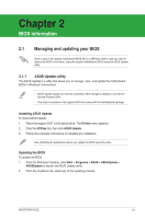
10.
Parallel port connector (26-1 pin LPT)
This connector is for a parallel port. Connect the parallel port module cable to this
connector, then install the module to a slot opening at the back of the system chassis.
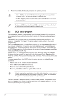
11.
Serial port connector (10-1 pin COM)
This connector is for a serial (COM) port. Connect the serial port module cable to this
connector, then install the module to a slot opening at the back of the system chassis.
P5G41-M LE Parallel Port Connector
PIN 1
LPT
SLCT
PE
BUSY
ACK#
PD7
PD6
PD5
PD4
PD3
PD2
PD1
PD0
STB#
GND
GND
GND
GND
GND
GND
GND
GND
SLIN#
INIT#
ERR#
AFD
P5G41-M LE
P5G41-M LE Serial port (COM1) connector
PIN 1
COM1
P5G41-M LE