Asus P5GC User Manual - Page 35
System memory
 |
View all Asus P5GC manuals
Add to My Manuals
Save this manual to your list of manuals |
Page 35 highlights
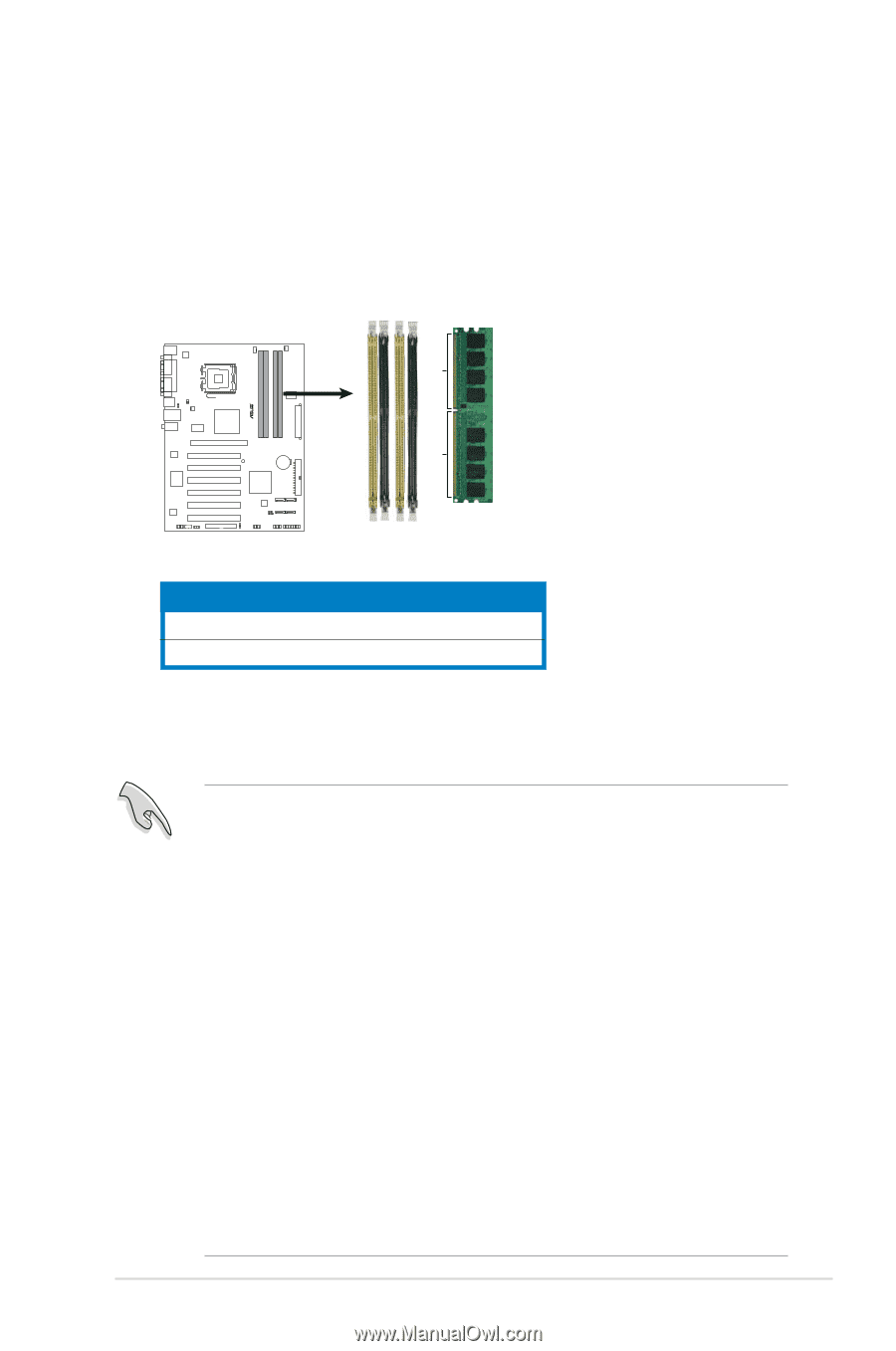
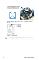
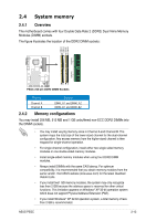
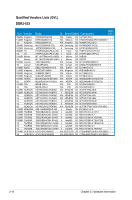
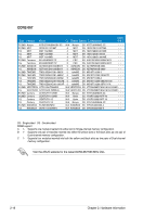
2.4 System memory 2.4.1 Overview The motherboard comes with four Double Data Rate 2 (DDR2) Dual Inline Memory Modules (DIMM) sockets. The figure illustrates the location of the DDR2 DIMM sockets: DIMM_A1 DIMM_A2 DIMM_B1 DIMM_B2 112 Pins P5GC 128 Pins P5GC.240-pin.DDR2.DIMM.Sockets Channel Sockets Channel A Channel B DIMM_A1 and DIMM_A2 DIMM_B1 and DIMM_B2 2.4.2 Memory configurations You may install 256 MB, 512 MB and 1 GB unbuffered non-ECC DDR2 DIMMs into the DIMM sockets. • You may install varying memory sizes in Channel A and Channel B. The system maps the total size of the lower-sized channel for the dual-channel configuration. Any excess memory from the higher-sized channel is then mapped for single-channel operation. • For single-channel configuration, install either two single-sided memory modules or one double-sided memory modules. • Install single-sided memory modules when using four DDR2 DIMM modules. • Always install DIMMs with the same CAS latency. For optimum compatibility, it is recommended that you obtain memory modules from the same vendor. Visit ASUS websie (www.asus.com) for the latest Qualified Vendor Lists. • If you install two1 GB memory modules, the system may only recognize less than 2 GB because the address space is reserved for other critical functions. This limitation appears on Windows® XP 32-bit operation system which does not support Physical Address Extension (PAE). • If you install Windows® XP 32-bit operation system, a total memory of less than 2 GB is recommended. ASUS P5GC 2-13
-
 1
1 -
2
-
3
-
4
-
5
-
6
-
7
-
8
-
9
-
10
-
11
-
12
-
13
-
14
-
15
-
16
-
17
-
18
-
19
-
20
-
21
-
22
-
23
-
24
-
25
-
26
-
27
-
28
-
29
-
 30
30 -
 31
31 -
 32
32 -
 33
33 -
 34
34 -
 35
35 -
 36
36 -
 37
37 -
 38
38 -
 39
39 -
 40
40 -
41
-
42
-
43
-
44
-
45
-
46
-
47
-
48
-
49
-
50
-
51
-
52
-
53
-
54
-
55
-
56
-
57
-
58
-
59
-
60
-
61
-
62
-
63
-
64
-
65
-
66
-
67
-
68
-
69
-
70
-
71
-
72
-
73
-
74
-
75
-
76
-
77
-
78
-
79
-
80
-
81
-
82
-
83
-
84
-
85
-
86
-
87
-
88
-
89
-
90
-
91
-
92
-
93
-
94
-
95
-
96
-
97
-
98
-
99
-
100
-
101
-
102
-
103
-
104
-
105
-
106
-
107
-
108
-
109
-
110
 |
 |