Asus P5GD2 Deluxe Motherboard Installation Guide - Page 2
Installation du Processeur, Schéma de la Carte Mère
 |
View all Asus P5GD2 Deluxe manuals
Add to My Manuals
Save this manual to your list of manuals |
Page 2 highlights
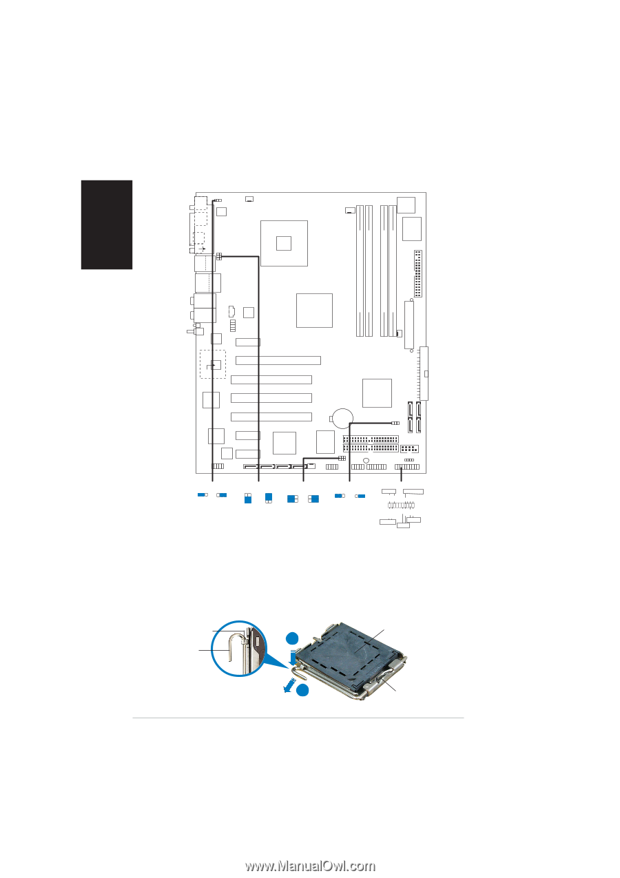
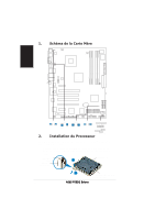
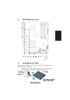
1. Schéma de la Carte Mère MS1 KBPWR1 CHA_FAN2 ATX12V1 CPU_FAN1 Intel FWH 8Mbit Super I/O FLOPPY1 DDR2 DIMM_B2 (64 bit,240-pin module) DDR2 DIMM_B1 (64 bit,240-pin module) P5GD2 DDR2 DIMM_A1 (64 bit,240-pin module) DDR2 DIMM_A2 (64 bit,240-pin module) SPDIF_O2 PARALLEL PORT KB1 Français USBPW34 USBPW12 SPDIF_O Bottom: USB1 USB2 Top: 1394 USB2.0 Top: T: USB3 RJ-45 B: USB4 Top:Rear Speaker Out Center: Side Speaker Out Below: Center/Subwoofer Top:Line In Center:Line Out Below:Mic In WL_LED WL_ANT C-Media CMI9880 Marvell 88E8053 CD AAFP PCIEX1_1 Intel 915P PRI_IDE1 PWR_FAN1 EATXPWR1 88W8000G Marvell 88W8310 PCIEX16 PCI1 PCI2 Intel ICH6R SATA1 SATA2 SATA3 SATA4 PCI3 TSB43AB22A PCIEX1_2 Speech Controller PCIEX1_3 Silicon Image SiL 3114R ITE 8212F CR2032 3V Lithium Cell CMOS Power CLRTC1 SEC_RAID1 PRI_RAID1 COM1 USBPW56 USBPW78 SB_PWR1 CHASSIS1 IE1394_2 SATA_RAID1 SATA_RAID2 SATA_RAID3 SATA_RAID4 CHA_FAN1 USB56 USB78 GAME1 PANEL1 2. KBPWR1 12 23 +5V +5VSB (Default) USBPW12 USBPW34 2 1 +5V (Default) 3 2 +5VSB USBPW56 USBPW78 12 23 +5V (Default) +5VSB CLRTC1 12 23 Normal (Default) Clear CMOS PLED+ PLED+5V Ground Ground Speaker PANEL1 PLED SPEAKER IDE_LED+ IDE_LED- PWR Ground Reset Ground IDE_LED RESET PWR * Requires an ATX power supply. Installation du Processeur Suivez cette procédure pour installer un processeur Intel® Pentium® 4 dans le paquet 775-land. 1. Appuyez sur le levier de chargement avec votre pouce (A), puis déplacez-le vers le gauche (B) jusqu'à ce qu'il soit détaché de la languette de retenue. Languette de retenue A Levier de chargement Capuchon PnP B Ce côté du boîtier cam doit être face à vous. 2 ASUS P5GD2 Deluxe
-
 1
1 -
 2
2 -
 3
3 -
 4
4 -
 5
5 -
 6
6 -
 7
7 -
 8
8 -
9
-
10
-
11
-
12
-
13
-
14
-
15
-
16
 |
 |