Asus P5KPL-AM User Manual - Page 47
Front panel audio connector 10-1 pin AAFP, Chassis intrusion connector 4-1 pin CHASSIS
 |
UPC - 890552664375
View all Asus P5KPL-AM manuals
Add to My Manuals
Save this manual to your list of manuals |
Page 47 highlights
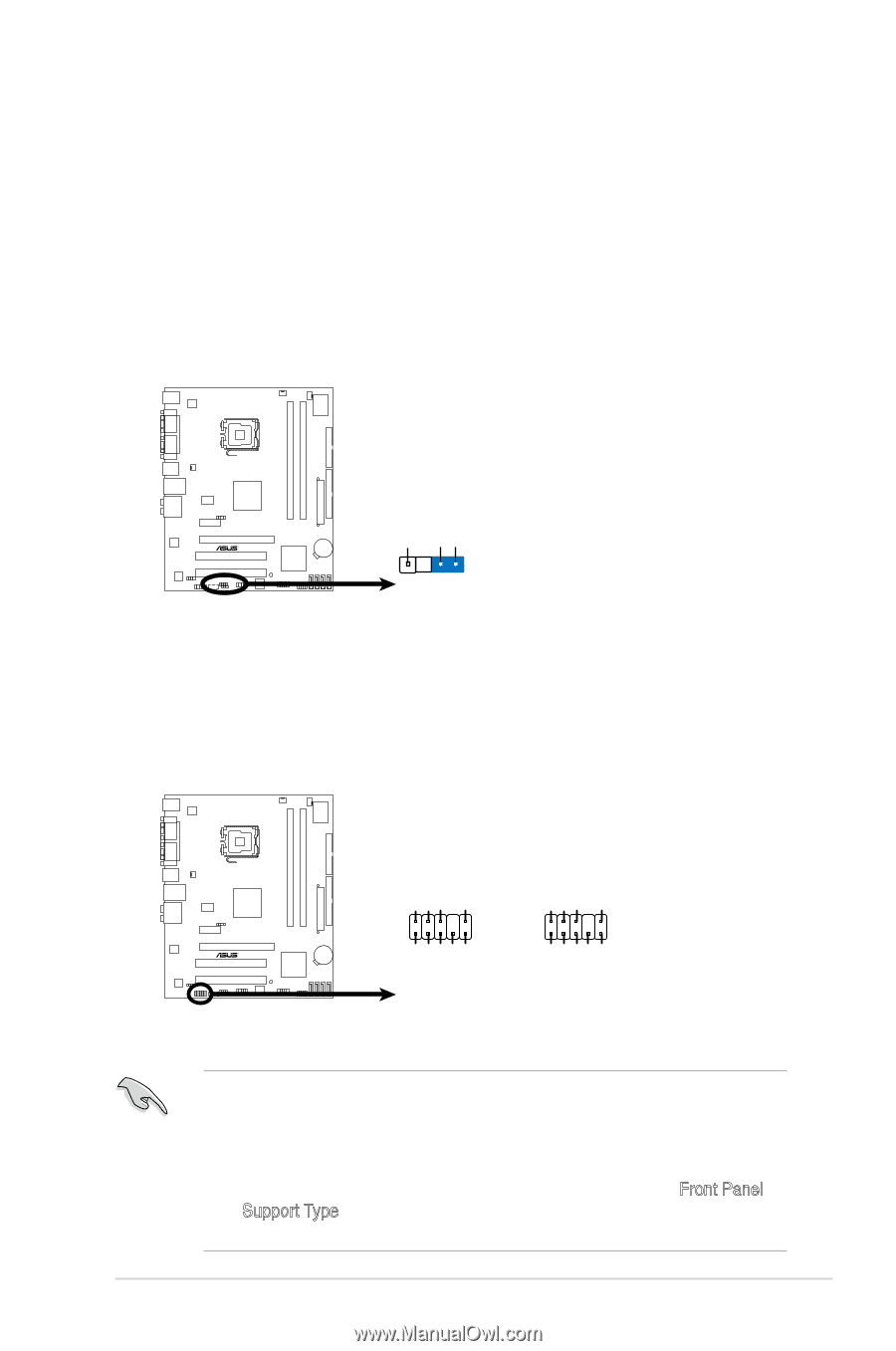
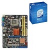
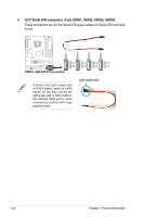
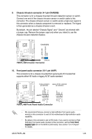
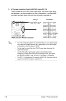
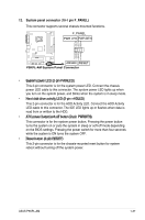
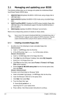
9. Chassis intrusion connector (4-1 pin CHASSIS) This connector is for a chassis-mounted intrusion detection sensor or switch. Connect one end of the chassis intrusion sensor or switch cable to this connector. The chassis intrusion sensor or switch sends a high-level signal to this connector when a chassis component is removed or replaced. The signal is then generated as a chassis intrusion event. By default , the pin labeled "Chassis Signal" and " Ground" are shorted with a jumper cap. Remove the jumper caps only when you intend to use the chassis intrusion detection feature. CHASSIS P5KPL-AM +5VSB_MB Chassis Signal GND (Default) P5KPL-AM Intrusion Connector 10. Front panel audio connector (10-1 pin AAFP) This connector is for a chassis-mounted front panel audio I/O module that supports either HD Audio or legacy AC'97 audio standard. Azalia-compliant Legacy AC'97-compliant pin definition pin definition AGND PRESENSE# MIC2_JD HP_HD AGND NC NC NC P5KPL-AM AAFP MIC2_L MIC2_R Line out_R NC Line out_L MIC2_L MIC2_R HP_R Jack_Sense HP_L P5KPL-AM Front Panel Audio Connector • We recommend that you connect a high-definition front panel audio module to this connector to avail of the motherboard's high-definition audio capability. • By default, this connector is set to HD Audio. If you want to connect a High Definition front panel audio module to this connector, set the Front Panel Support Type item in the BIOS to [HD Audio]. See section "2.4.4 Chipset" for details. ASUS P5KPL-AM 1-35
-
 1
1 -
2
-
3
-
4
-
5
-
6
-
7
-
8
-
9
-
10
-
11
-
12
-
13
-
14
-
15
-
16
-
17
-
18
-
19
-
20
-
21
-
22
-
23
-
24
-
25
-
26
-
27
-
28
-
29
-
30
-
31
-
32
-
33
-
34
-
35
-
36
-
37
-
38
-
39
-
40
-
41
-
 42
42 -
 43
43 -
 44
44 -
 45
45 -
 46
46 -
 47
47 -
 48
48 -
 49
49 -
 50
50 -
 51
51 -
 52
52 -
53
-
54
-
55
-
56
-
57
-
58
-
59
-
60
-
61
-
62
-
63
-
64
-
65
-
66
-
67
-
68
-
69
-
70
-
71
-
72
-
73
-
74
-
75
-
76
-
77
-
78
-
79
-
80
-
81
-
82
-
83
-
84
-
85
-
86
-
87
-
88
-
89
-
90
-
91
-
92
 |
 |