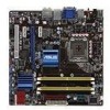
Asus P5Q EM User Manual
Asus P5Q EM - DO Motherboard - Micro ATX Manual
 |
UPC - 610839167241
View all Asus P5Q EM manuals
Add to My Manuals
Save this manual to your list of manuals |
Asus P5Q EM manual content summary:
- Asus P5Q EM | User Manual - Page 1
P5Q-EM Motherboard - Asus P5Q EM | User Manual - Page 2
express written permission of ASUSTeK COMPUTER INC. ("ASUS"). Product warranty or service will not be extended if: (1) the ASUS HAS BEEN ADVISED OF THE POSSIBILITY OF SUCH DAMAGES ARISING FROM ANY DEFECT OR ERROR IN THIS MANUAL OR PRODUCT. SPECIFICATIONS AND INFORMATION CONTAINED IN THIS MANUAL - Asus P5Q EM | User Manual - Page 3
vii About this guide viii P5Q-EM specifications summary x Chapter 1: Product introduction 1.1 Welcome 1-2 1.2 Package contents 1-2 1.3 Special features 1-3 1.3.1 Product highlights 1-3 1.3.2 ASUS unique features 1-5 1.3.3 ASUS Intelligent Performance & Overclocking features.. 1-7 1.4 Before - Asus P5Q EM | User Manual - Page 4
46 Chapter 2: BIOS setup 2.1 Managing and updating your BIOS 2-2 2.1.1 ASUS Update utility 2-2 2.1.2 Creating a bootable floppy disk 2-5 2.1.3 ASUS EZ Flash 2 utility 2-6 2.1.4 AFUDOS utility 2-7 2.1.5 ASUS CrashFree BIOS 3 utility 2-9 2.2 BIOS setup program 2-10 2.2.1 BIOS menu screen 2-11 - Asus P5Q EM | User Manual - Page 5
Running the support DVD 3-2 3.2.2 Drivers menu 3-3 3.2.3 Utilities menu 3-4 3.2.4 Make disk menu 3-6 3.2.5 Manual menu 3-7 3.2.6 ASUS Contact information 3-7 3.2.7 Other information 3-8 3.3 ASUS Express Gate 3-10 3.4 Creating a RAID driver disk 3-19 3.4.1 Creating a RAID driver disk without - Asus P5Q EM | User Manual - Page 6
. This equipment generates, uses and can radiate radio frequency energy and, if not installed and used in accordance with manufacturer's instructions, may cause harmful interference to radio communications. However, there is no guarantee that interference will not occur in a particular installation - Asus P5Q EM | User Manual - Page 7
qualified service technician or your retailer. Operation safety • Before installing the motherboard and adding devices on it, carefully read all the manuals stable surface. • If you encounter technical problems with the product, contact a qualified service technician or your retailer. This symbol of - Asus P5Q EM | User Manual - Page 8
the BIOS parameters are also provided. • Chapter 3: Software support This chapter describes the contents of the support DVD that comes with the motherboard package. Where to find more information Refer to the following sources for additional information and for product and software updates. 1. ASUS - Asus P5Q EM | User Manual - Page 9
the following symbols used throughout this manual. DANGER/WARNING: Information to prevent injury to yourself when trying to complete a task. CAUTION: Information to prevent damage to the components when trying to complete a task. IMPORTANT: Instructions that you MUST follow to complete - Asus P5Q EM | User Manual - Page 10
P5Q-EM specifications summary CPU Chipset System bus Memory VGA Expansion slots Storage LAN Audio IEEE 1394 USB LGA775 socket for Intel® Core™2 Extreme / Core™2 Quad / Core™2 Duo / Pentium® dual-core / Celeron® dualcore / Celeron® processors Compatible with Intel® 05B/05A/06 processors Supports - Asus P5Q EM | User Manual - Page 11
P5Q-EM specifications summary ASUS Unique features Other features ASUS Exclusive Overclocking features Rear panel connectors ASUS Power Saving solution: - ASUS EPU-4 Engine - AI Nap ASUS Express Gate ASUS Quiet Thermal Solution: - ASUS Fanless Design - ASUS Fan Xpert ASUS Crystal Sound: - ASUS - Asus P5Q EM | User Manual - Page 12
P5Q-EM specifications summary Internal connectors BIOS features Manageability Support DVD contents Form factor 3 x USB connectors support 6 additional USB ports 1 x Floppy disk drive connector 1 x IDE connector 6 x SATA connectors 1 x CPU / 1 x Chassis / 1 x Power fan connectors 1 x IEEE1394a - Asus P5Q EM | User Manual - Page 13
This chapter describes the motherboard features and the new technologies it supports. 1Product introduction - Asus P5Q EM | User Manual - Page 14
. 1.2 Package contents Check your motherboard package for the following items. Motherboard ASUS P5Q-EM Cables 3 x S��A�T�A��s�i�g�n�a�l�c�a��b�le�s� 2 ASUS Q-Connector Kit (USB, 1394, system panel; Retail version only) Application DVD ASUS motherboard support DVD Documentation User guide - Asus P5Q EM | User Manual - Page 15
specification, delivering enhanced scalability and doubling the bus bandwidth for high-speed data retrieval and saves. The onboard Intel® ICH10R allows RAID 0, RAID 1, RAID 5, and RAID 10 configurations for six SATA connectors. �S�e�e��p�a��g�e��1�-�3�6��f�o�r�d��e�ta��il�s�. ASUS P5Q-EM 1-3 - Asus P5Q EM | User Manual - Page 16
cable for full HD 1080p visuals. Supporting HDCP copy protection such as HD DVD and Blu-ray Discs, HDMI provides you with the highest �S�e�e��p�a��g�e��1�-�3�0��f�o�r�d��e�ta��il�s�. S/PDIF digital sound ready This motherboard provides convenient connectivity to external home theater audio systems - Asus P5Q EM | User Manual - Page 17
power and noise when you are temporarily away. To wake the system and return to the OS environment, simply click the mouse or press a key. ASUS Quiet Thermal Solution ASUS Quiet Thermal solution makes system more stable and enhances the overclocking capability. ASUS P5Q-EM 1-5 - Asus P5Q EM | User Manual - Page 18
easy ways to install computer components, update the BIOS or back up your favorite settings. ASUS Q-Connector ASUS Q-Connector allows you to easily connect or disconnect the chassis front panel cables to the motherboard. This unique module eliminates the trouble of connecting the system panel cables - Asus P5Q EM | User Manual - Page 19
the system hangs due to overclocking. When the system hangs due to overclocking, C.P.R. eliminates the need to open the system chassis and clear the RTC data. Simply shut down and reboot the system, and the BIOS automatically restores the CPU default setting for each parameter. ASUS P5Q-EM 1-7 - Asus P5Q EM | User Manual - Page 20
1-8 Chapter 1: Product Introduction - Asus P5Q EM | User Manual - Page 21
in soft‑off mode. This is a reminder that you should shut down the system and unplug the power cable before removing or plugging in any motherboard component. The illustration below shows the location of the onboard LED. ASUS P5Q-EM 1-9 - Asus P5Q EM | User Manual - Page 22
1.5 Motherboard overview 1.5.1 Motherboard layout Refer to 1.10 Connectors for more information about rear panel connectors and internal connectors. 1-10 Chapter 1: Product introduction - Asus P5Q EM | User Manual - Page 23
) 19. Digital audio connector (4-1 pin SPDIF_OUT) Page 1-29 1-42 1-14 1-19 1-39 1-34 1-38 1-35 1-36 1-28 1-43 1-40 1-9 1-37 1-29 1-38 1-41 1-41 1-40 ASUS P5Q-EM 1-11 - Asus P5Q EM | User Manual - Page 24
in the image below. 1.5.4 Screw holes Place eight (8) screws into the holes indicated by circles to secure the motherboard to the chassis. DO NOT overtighten the screws! Doing so can damage the motherboard. Place this side towards the rear of the chassis 1-12 Chapter 1: Product introduction - Asus P5Q EM | User Manual - Page 25
Merchandise Authorization (RMA) requests only if the motherboard comes with the cap on the LGA775 socket. • The product warranty does not cover damage to the socket contacts resulting from incorrect CPU installation/removal, or misplacement/loss/ incorrect removal of the PnP cap. ASUS P5Q-EM 1-13 - Asus P5Q EM | User Manual - Page 26
1.6.1 Installing the CPU To install a CPU: 1. Locate the CPU socket on the motherboard. Before installing the CPU, make sure that the cam box is facing towards (4A), then push the PnP cap from the load plate window to remove (4B). PnP cap Load plate 4B 4A 3 1-14 Chapter 1: Product introduction - Asus P5Q EM | User Manual - Page 27
alignment key into the CPU notch. The CPU fits in only one correct orientation. DO NOT force the CPU into the socket to prevent bending the connectors on the socket and damaging the CPU! CPU notch Alignment key 6. the paste, DO NOT spread the paste with your finger directly. ASUS P5Q-EM 1-15 - Asus P5Q EM | User Manual - Page 28
then push the load lever (B) until it snaps into A the retention tab. B The motherboard supports Intel® LGA775 processors with the Intel® Enhanced Memory 64 Technology (EM64T), Enhanced Intel SpeedStep® Technology (EIST), and Hyper-Threading Technology. Refer to the Appendix for more information - Asus P5Q EM | User Manual - Page 29
match the holes on the motherboard. B 2. Push down two fasteners at a time in a diagonal sequence to secure the heatsink and fan assembly in place. A B A A B B A 1 1 Orient the heatsink and fan assembly such that the CPU fan cable is closest to the CPU fan connector. ASUS P5Q-EM 1-17 - Asus P5Q EM | User Manual - Page 30
CPU fan cable to the connector on the motherboard labeled CPU_FAN. DO NOT forget to connect the CPU fan connector! Hardware monitoring errors can occur if you fail to plug this connector. 1.6.3 Uninstalling the CPU heatsink and fan To uninstall the CPU heatsink and fan: 1. Disconnect the CPU fan - Asus P5Q EM | User Manual - Page 31
1.7 System memory 1.7.1 Overview The motherboard comes with four Double Data Rate 2 (DDR2) Dual Inline Memory Modules (DIMM) sockets. A DDR2 module has the same physical dimensions as a DDR DIMM sockets: Channel Channel A Channel B Sockets DIMM_A1 and DIMM_A2 DIMM_B1 and DIMM_B2 ASUS P5Q-EM 1-19 - Asus P5Q EM | User Manual - Page 32
3 GB is recommended. • This motherboard does not support memory modules made up of 256 Mb chips. • Due to chipset limitation, this motherboard can only support up to 16 GB on the operating systems listed below. You may install a maximum of 4 GB DIMMs on each slot. 64-bit Windows® XP Professional x64 - Asus P5Q EM | User Manual - Page 33
5 DIMM support A* B* C* • • •• • • • ••• • • ••• ••• •• • ••• • • •• •• • •• • • • • • P5Q-EM Motherboard Qualified Vendors N/A N/A 5 N/A 4-4-4-12 N/A 4 4 4 4 5 5-5-5-15 N/A N/A 4 N/A 5 6 6-6-6-18 N/A N/A DIMM support A* B* C ••• ••• •• ASUS P5Q-EM 1-21 - Asus P5Q EM | User Manual - Page 34
GEIL GEIL GEIL GEIL GEIL GEIL GEIL GEIL GEIL GEIL GEIL GEIL GEIL GEIL GEIL GEIL GEIL GEIL GEIL GEIL Hynix Hynix KINGMAX KINGMAX KINGMAX KINGSTON KINGSTON KINGSTON KINGSTON KINGSTON KINGSTON KINGSTON KINGSTON KINGSTON KINGSTON KINGSTON KINGSTON NANYA NANYA NANYA NANYA OCZ OCZ OCZ OCZ OCZ PSC Qimonda - Asus P5Q EM | User Manual - Page 35
P5Q-EM Motherboard Qualified Vendors Lists (QVL) DDR2-667MHz capability memory configuration. • C*: Supports four modules inserted into both the yellow and black slots as two pairs of Dual-channel memory configuration. Visit the ASUS website for the latest DDR2-1066/800/667MHz QVL. ASUS P5Q-EM - Asus P5Q EM | User Manual - Page 36
system components. Failure to do so may cause severe damage to both the motherboard and the components. To install a DIMM 1. Unlock a DDR2 DIMM socket retaining clips outward to unlock the DIMM. 1 DDR2 DIMM notch Support the DIMM lightly with your fingers when pressing the retaining clips. - Asus P5Q EM | User Manual - Page 37
cover (if your motherboard is already installed in drivers support "Share IRQ" or that the cards do not need IRQ assignments. Otherwise, conflicts will arise between the two PCI groups, making the system unstable and the card inoperable. Refer to the table on the next page for details. ASUS P5Q-EM - Asus P5Q EM | User Manual - Page 38
steering* * These IRQs are usually available for PCI devices. IRQ assignments for this motherboard A B C D E F G H 1394 (FW3227) - - - shared - - - - LAN (8111C) - shared - - - - - - Marvell 6102 shared - - - - - - - PCIEX16_1 shared - - - - - - - PCIEX1_1 - Asus P5Q EM | User Manual - Page 39
PCI Express 2.0 x16 slot This motherboard has a PCI Express 2.0 x16 slot that supports PCI Express 2.0 x16 graphics cards complying with the PCI Express specifications. Refer to the figure below for the location of the slot. PCI slot PCIe x1 slot PCIe 2.0 x16 slot PCIe x1 slot ASUS P5Q-EM 1-27 - Asus P5Q EM | User Manual - Page 40
CMOS RTC RAM data. After the CMOS clearance, reinstall the battery. • You do not need to clear the RTC when the system hangs due to overclocking. For system failure due to overclocking, use the C.P.R. (CPU Parameter Recall) feature. Shut down and reboot the system so the BIOS can automatically reset - Asus P5Q EM | User Manual - Page 41
least 1A on the +5VSB lead, and a corresponding setting in the BIOS. The USBPW56 jumper is for the internal USB connectors that you can jumpers to +5V to wake up the computer from S1 sleep mode (CPU stopped, DRAM refreshed, system running in low power mode) using the connected ASUS P5Q-EM 1-29 - Asus P5Q EM | User Manual - Page 42
1.10 Connectors 1.10.1 Rear panel connectors 1. PS/2 keyboard / mouse combo port. This port is for a PS/2 keyboard or mouse. 2. IEEE 1394a port. This 6-pin IEEE 1394a port provides high-speed connectivity for audio/video devices, storage peripherals, PCs, or portable devices. 3. Video Graphics - Asus P5Q EM | User Manual - Page 43
of HD DVD, Blu-Ray and other protected content. • This motherboard comes with multiple VGA output that features desktop extension on two monitors. HDMI ports. Note that DVI-D/HDMI dual output works in OS environment only and that during POST or BIOS setup, only DVI-D output is valid. ASUS P5Q-EM - Asus P5Q EM | User Manual - Page 44
to the Intel® driver issue, some monitor resolution settings will lead to monitor overscan or underscan. Refer to the next page for the troubleshooting on monitor overscan/underscan problem • Playback of HD DVD and Blu-Ray Discs The speed and bandwidth of the CPU/Memory, DVD player, and drivers will - Asus P5Q EM | User Manual - Page 45
Troubleshooting on monitor overscan/underscan problem 1. Install Intel Graphics Accelerator Driver from the motherboard support DVD. 2. From the Windows® notification area, double-click the Intel(R) Graphics Media Accelerator Driver icon and click Graphics Properties. 3. Click Display Settings and - Asus P5Q EM | User Manual - Page 46
1.10.2 Internal connectors 1. Floppy disk drive connector (34-1 pin FLOPPY) This connector is for the provided floppy disk drive (FDD) signal cable. Insert one end of the cable to this connector, then connect the other end to the signal connector at the back of the floppy disk drive. Pin 5 on the - Asus P5Q EM | User Manual - Page 47
Ultra DMA 133/100/66 signal cable: blue, black, and gray. Connect the blue connector to the motherboard's IDE connector, then select one of the following modes to configure your device. Single device Two devices -Select," make sure all other device jumpers have the same setting. ASUS P5Q-EM 1-35 - Asus P5Q EM | User Manual - Page 48
with the Intel® Matrix Storage Technology through the onboard Intel® ICH10R RAID BIOS to [RAID]. See section 2.3.5 Storage Configuration for details. • Before creating a RAID set, refer to the manual bundled in the motherboard support DVD. • You must install the Windows® XP/Vista Service - Asus P5Q EM | User Manual - Page 49
your chassis supports front panel USB ports, you can attach a front panel USB cable to these connectors. Connect the USB cable to ASUS Q-Connector (USB, blue) first, and then install the Q-Connector (USB) to the USB connector onboard. The USB module cable is purchased separately. ASUS P5Q-EM 1-37 - Asus P5Q EM | User Manual - Page 50
USB cable to the IEEE 1394a connector. Doing so will damage the motherboard! You can attach a FireWire/1394 cable to this connector if your chassis suppots the front panel IEEE1394 port. Connect the 1394 cable to ASUS Q-Connector (1394, red) first, and then install the Q-Connector (1394 - Asus P5Q EM | User Manual - Page 51
to connect the fan cables to the fan connectors. Insufficient air flow inside the system may damage the motherboard components. These are not jumpers! Do not place jumper caps on the fan connectors! Only the CPU_FAN and CHA_FAN 1 connectors support the ASUS Fan Xpert feature. ASUS P5Q-EM 1-39 - Asus P5Q EM | User Manual - Page 52
8. Chassis intrusion connector (4-1 pin CHASSIS) This connector is for a chassis-mounted intrusion detection sensor or switch. Connect one end of the chassis intrusion sensor or switch cable to this connector. The chassis intrusion sensor or switch sends a high-level signal to this connector when a - Asus P5Q EM | User Manual - Page 53
chassis-mounted front panel audio I/O module that supports either HD Audio or legacy AC`97 module to this connector to avail of the motherboard's high-definition audio capability. • If you make sure that the Front Panel Type item in the BIOS is set to [HD Audio]. If you want to ASUS P5Q-EM 1-41 - Asus P5Q EM | User Manual - Page 54
that you use a power supply unit (PSU) that complies with ATX 12 V Specification 2.0 (or later version) and provides a minimum power of 400 W. • Do the Recommended Power Supply Wattage Calculator at http://support.asus.com/PowerSupplyCalculator/PSCalculator. aspx?SLanguage=en-us for - Asus P5Q EM | User Manual - Page 55
connector supports several BIOS settings. Pressing the power switch for more than four seconds while the system is ON turns the system OFF. • Reset button (2-pin RESET) This 2-pin connector is for the chassis-mounted reset button for system reboot without turning off the system power. ASUS P5Q-EM - Asus P5Q EM | User Manual - Page 56
a few steps. Refer to the instructions below to install the ASUS QConnector. 1. Connect the front panel cables to the ASUS Q-Connector. Refer to the labels 2. Install the ASUS Q-Connector to the system panel connector, making sure the orientation matches the labels on the motherboard. 3. The front - Asus P5Q EM | User Manual - Page 57
beep followed by four short beeps Description VGA detected Quick boot set to disabled No keyboard detected No memory detected No VGA detected Hardware component failure 7. At power on, hold down the key to enter the BIOS Setup. Follow the instructions in Chapter 2. ASUS P5Q-EM 1-45 - Asus P5Q EM | User Manual - Page 58
Turn Off button to shut down the computer. 3. The power supply should turn off after Windows® shuts down. 1.12.2 Using the dual function power switch While the system is ON mode or to soft-off mode, depending on the BIOS setting. Pressing the power switch for more than four seconds lets the system - Asus P5Q EM | User Manual - Page 59
This chapter tells how to change the Chapter 2: BIOS se2tup system settings through the BIOS Setup menus. Detailed descriptions of the BIOS parameters are also provided. - Asus P5Q EM | User Manual - Page 60
(Updates the BIOS in Windows® environment.) 2. ASUS EZ Flash 2 (Updates the BIOS using a floppy disk or USB flash disk.) 3. ASUS AFUDOS (Updates the BIOS using a bootable floppy disk) 4. ASUS CrashFree BIOS 3 (Updates the BIOS using a bootable floppy disk, USB flash disk or the motherboard support - Asus P5Q EM | User Manual - Page 61
Start > Programs > ASUS > ASUSUpdate > ASUSUpdate. The ASUS Update main window appears. 2. Select Update BIOS from the 3. Select the ASUS FTP site nearest Internet option from the drop‑down you to avoid network traffic, or menu, then click Next. click Auto Select. Click Next. ASUS P5Q-EM 2-3 - Asus P5Q EM | User Manual - Page 62
. The ASUS Update main window appears. 2. Select Update BIOS from a file option from the drop‑down menu, then click Next. 3. Locate the BIOS file from the Open window, then click Open. 4. Follow the screen instructions to complete the update process. P5QEM.ROM P5QEM 2-4 Chapter 2: BIOS setup - Asus P5Q EM | User Manual - Page 63
type format A:/S then press . Windows® XP environment a. Insert a 1.44 MB floppy disk to the floppy disk drive. b. Click Start from the Windows® desktop, then select My Computer. c. Start. 2. Copy the original or the latest motherboard BIOS file to the bootable floppy disk. ASUS P5Q-EM 2-5 - Asus P5Q EM | User Manual - Page 64
is accessible by pressing + during the Power-On Self Tests (POST). To update the BIOS using EZ Flash 2 1. Visit the ASUS website (www.asus.com) to download the latest BIOS file for the motherboard. 2. Save the BIOS file to a floppy disk or a USB flash disk, then restart the system. 3. You - Asus P5Q EM | User Manual - Page 65
returns to the DOS prompt after copying the current BIOS file. Updating the BIOS file To update the BIOS file using the AFUDOS utility: 1. Visit the ASUS website (www.asus.com) and download the latest BIOS file for the motherboard. Save the BIOS file to a bootable floppy disk. ASUS P5Q-EM 2-7 - Asus P5Q EM | User Manual - Page 66
You need to type the exact BIOS filename at the DOS prompt. 2. Copy the AFUDOS utility (afudos.exe) from the motherboard support DVD to the bootable floppy disk reset the system while updating the BIOS to prevent system boot failure! 5. The utility returns to the DOS prompt after the BIOS update - Asus P5Q EM | User Manual - Page 67
the updating process. • Only the USB flash disk with FAT 32/16 format and single partition can support ASUS CrashFree BIOS 3. The device size should be smaller than 8GB. • DO NOT shut down or reset the system while updating the BIOS! Doing so can cause system boot failure! ASUS P5Q-EM 2-9 - Asus P5Q EM | User Manual - Page 68
motherboard supports a programmable firmware chip that you can update using the provided utility described in section 2.1 Managing and updating your BIOS. Use the BIOS Setup program when you are installing a motherboard , or by pressing the reset button on the system chassis. You can - Asus P5Q EM | User Manual - Page 69
Menu items Menu bar Configuration fields Main Ai Tweaker BIOS SETUP UTILITY Advanced Power Boot General help Tools Exit System changing the basic system configuration For changing the overclocking settings For changing the advanced system settings For screen to another. ASUS P5Q-EM 2-11 - Asus P5Q EM | User Manual - Page 70
menu bar displays the specific items for that menu to 2.2.7 Pop-up window. 2.2.7 Pop-up window Select a menu item then press to display a pop-up window with the configuration options the other items on the screen. Pop-up window Scroll bar 2.2.9 General help At the top right corner of the - Asus P5Q EM | User Manual - Page 71
information on the menu screen items and how to navigate through them. Main Ai Tweaker BIOS SETUP UTILITY Advanced Power Boot Tools Exit System Time [11:55:25] System Date type of floppy drive installed. Configuration options: [Disabled] [720K , 2.5 in.] [1.44M, 2.5 in.] ASUS P5Q-EM 2-13 - Asus P5Q EM | User Manual - Page 72
information. Main BIOS SETUP UTILITY SATA 1 Device : Hard Disk Vendor : WDC WD800JD-00LSA0 Size : 80.0GB LBA Mode : Supported Block Mode : of the appropriate IDE device type. Select [CDROM] if you are specifically configuring a CD-ROM drive. Select [ARMD] (ATAPI Removable Media Device - Asus P5Q EM | User Manual - Page 73
Main BIOS SETUP supported by the Southbridge chip. Configuration options: [IDE] [RAID] [AHCI AHCI), set this item to [AHCI]. The AHCI allows the onboard storage driver Intel® Matrix Storage Technology configuration from the Serial ATA hard disk drives, set this item to [RAID]. ASUS P5Q-EM 2-15 - Asus P5Q EM | User Manual - Page 74
only when you set the item Configure SATA as from the sub-menu of SATA Configuration to [AHCI]. Main BIOS SETUP UTILITY AHCI Settings AHCI CD/DVD Boot Time out [35] Some SATA CD/DVD in AHCI mode need to wait ready longer. SATA Port1 [Not Detected] SATA Port2 [Not Detected] SATA Port3 [Not - Asus P5Q EM | User Manual - Page 75
Item F1 General Help F10 Save and Exit ESC Exit v02.61 (C)Copyright 1985-2008, American Megatrends, Inc. Bios Information Displays the auto-detected BIOS information. Processor Displays the auto-detected CPU specification. System Memory Displays the auto-detected system memory. ASUS P5Q-EM 2-17 - Asus P5Q EM | User Manual - Page 76
CPU and memory modules you install on the motherboard. Main Ai Tweaker BIOS SETUP UTILITY Advanced Power Boot Tools Exit Configure System Performance Settings Ai Overclock Tuner [Auto] CPU Please key in numbers directly! ******** Options Manual Auto Select Screen Select Item Enter Go to - Asus P5Q EM | User Manual - Page 77
DDR2 800, you can manually adjust DRAM Frequency. T�h��e�f�o�l�lo��w�i�n�g��ta��b�le��s�h�o��w�s��t�h�e��v�a�r�ia�t�i�o�n��o�f DRAM Frequency configuration options according to FSB Frequency settings. FSB Auto 667 1600 • 1333 • • 1066 • • 800 • • ASUS P5Q-EM DRAM Frequency (MHz) 800 - Asus P5Q EM | User Manual - Page 78
the DRAM Timing Control item to [Manual]. • The configuration options for some of the following items vary depending on the DIMMs you install on the motherboard. 1st Information : 5-5-5-15-3-44-5-3 (S) [Auto] Configuration options: [Auto] [1 DRAM Clocks]-[15 DRAM Clocks] 2-20 Chapter 2: BIOS setup - Asus P5Q EM | User Manual - Page 79
] [Disabled] [Enabled] MEM. OC Charger [Auto] Enable this item to increase DRAM overclockability. Configuration options: [Auto] [Disabled] [Enabled] Ai Clock Twister [Auto] Allows you to performance. Configuration options: [Auto] [Lighter] [Light] [Moderate] [Strong] [Stronger] ASUS P5Q-EM 2-21 - Asus P5Q EM | User Manual - Page 80
to set the CPU PLL voltage. The values range from 1.50V to 2.20V with a 0.02V interval. FSB Termination Voltage [Auto] Allows you to set the front side bus termination voltage. The values range from 1.20V to 1.70V with a 0.02V interval. DRAM Voltage [Auto] Allows you to set the memory voltage. The - Asus P5Q EM | User Manual - Page 81
[Auto] Set to [Disabled] to enhance FSB overclocking ability or [Auto] for EMI control. Configuration options: [Auto] [Disabled] PCIE Spread Spectrum [Auto] Set to [Disabled] to enhance PCIE overclocking ability or [Auto] for EMI control. Configuration options: [Auto] [Disabled] ASUS P5Q-EM 2-23 - Asus P5Q EM | User Manual - Page 82
options: [Auto] [Normal] [Delay 100ps] [Delay 200ps]-[Delay 1500ps] NB Clock Skew [Auto] Configuration options: [Auto] [Normal] [Delay 100ps] [Delay 200ps]-[Delay 1500ps] CPU Margin Enhancement [Optimized] Configuration options: [Optimized] [Compatible] [Performance Mode] 2-24 Chapter - Asus P5Q EM | User Manual - Page 83
ratio between CPU Core Clock and the FSB Frequency. NOTE: If an invalid ratio is set in CMOS then actual and setpoint values may differ. Select Screen Select Item +- Change Option F1 General Help F10 Save and Exit ESC Exit v02.61 (C)Copyright 1985-2008, American Megatrends, Inc. ASUS P5Q-EM 2-25 - Asus P5Q EM | User Manual - Page 84
ry��d�e�p�e��n�d�i�n�g��o�n��th�e� CPU installed. Configuration options: [Auto] [06.0] [07.0]-[XX.X] C1E Support [Enabled] Allows you to enable or disable Enhanced Halt State support. Configuration options: [Disabled] [Enabled] Intel(R) Virtualization Tech [Enabled] The Intel® Virtualization - Asus P5Q EM | User Manual - Page 85
to set the GMCH Protected Audio Video Path (PAVP) BIOS support. Configuration options: [Disabled] [Lite Mode] [Paranoid] DVMT Memory [256MB] Configuration options: [128MB] [256MB] [Maximum DVMT] The [Maximum DVMT] option appears only when you install DIMM modules more than 1 GB. ASUS P5Q-EM 2-27 - Asus P5Q EM | User Manual - Page 86
This motherboard supports Intel® DVMT 5.0 Technology whose maximum graphics memory size in total varies with the system memory size in total and the operating system. Refer to the following table for details. System Memory 1GB to < 1.5GB 1GB to < 2GB 2GB to < 3GB 3GB to < 4GB 4GB and above Maximum - Asus P5Q EM | User Manual - Page 87
USB Devices Enabled: None BIOS SETUP UTILITY Advanced USB Functions USB 2.0 Controller USB 2.0 Controller Mode BIOS EHCI Hand-off Legacy USB Support [Enabled] [Enabled] [HiSpeed Enabled] The following items appear only when you set USB Functions to [Enabled]. ASUS P5Q-EM 2-29 - Asus P5Q EM | User Manual - Page 88
you enable the USB 2.0 Controller. BIOS EHCI Hand-off [Enabled] Allows you to enable the support for operating systems without an EHCI hand legacy mode is enabled. If no USB device is detected, the legacy USB support is disabled. Configuration options: [Disabled] [Enabled] [Auto] 2.5.5 PCIPnP The - Asus P5Q EM | User Manual - Page 89
you to enable or disable the Advanced Configuration and Power Interface (ACPI) support in the Advanced Programmable Interrupt Controller (APIC). When set to [Enabled], the ACPI APIC table pointer is included in the RSDT pointer list. Configuration options: [Disabled] [Enabled] ASUS P5Q-EM 2-31 - Asus P5Q EM | User Manual - Page 90
2.6.5 APM Configuration BIOS SETUP UTILITY Power APM Configuration Restore on AC Power Loss [Power Off] Power On By RTC Alarm [Disabled] Allows you to enable or disable the PCIE devices to generate a wake event. Configuration options: [Disabled] [Enabled] 2-32 Chapter 2: BIOS setup - Asus P5Q EM | User Manual - Page 91
If the fan is not connected to the motherboard, the field shows [N/A]. CPU Q-Fan Control [Enabled] Allows you to enable or disable the CPU Q-fan control feature. Configuration options: [Disabled] [Enabled] The following item appears only when you enable the CPU Q-Fan Control item. ASUS P5Q-EM 2-33 - Asus P5Q EM | User Manual - Page 92
maximum CPU fan speed. Configuration options: [Standard] [Silent] [Turbo] Chassis Fan 1 Speed [xxxxRPM] or [Ignored] / [N/A] The onboard hardware monitor automatically detects and displays the chassis fan speed in rotations per minute (RPM). If the fan is not connected to the motherboard, the - Asus P5Q EM | User Manual - Page 93
Save and Exit ESC Exit v02.61 (C)Copyright 1985-2008, American Megatrends, Inc. 2.7.1 Boot Device Priority BIOS SETUP UTILITY Boot Boot Device Priority 1st Boot Device 2nd Boot Device 3rd Boot Device [1st FLOPPY DRIVE : [1st FLOPPY DRIVE] [Hard Drive] [ATAPI CD-ROM] [Disabled] ASUS P5Q-EM 2-35 - Asus P5Q EM | User Manual - Page 94
Mode [Force BIOS] Bootup Num-Lock [On] Wait for 'F1' if Error [Enabled] Hit 'DEL' Message Display [Enabled] Allows BIOS to skip certain to use the ASUS MyLogo 2™ feature. AddOn ROM Display Mode [Force BIOS] Sets the display mode for option ROM. Configuration options: [Force BIOS] [Keep Current] - Asus P5Q EM | User Manual - Page 95
. If you forget your BIOS password, you can clear it by erasing the CMOS Real Time Clock (RTC) RAM. See section 1.9 Jumpers for information on how to erase the RTC RAM. After you have set a supervisor password, the other items appear to allow you to change other security settings. ASUS P5Q-EM 2-37 - Asus P5Q EM | User Manual - Page 96
BIOS SETUP UTILITY Boot Security Settings Supervisor Password User Password : Installed : password. Password Check [Setup] When set to [Setup], BIOS checks for user password when accessing the Setup utility. When set to [Always], BIOS checks for user password both when accessing Setup and booting - Asus P5Q EM | User Manual - Page 97
2 BIOS ROM Utility V3.25 FLASH TYPE: EON 25P/F80 Current ROM BOARD: P5Q-EM VER: 0138 DATE: 07/07/2008 Update ROM BOARD: Unknown VER: Unknown DATE: Unknown PATH: A:\ A: Note [Enter] Select or Load [Up/Down/Home/End] Move [Tab] Switch [B] Backup [V] Drive Info [Esc] Exit ASUS P5Q-EM 2-39 - Asus P5Q EM | User Manual - Page 98
or disable the ASUS Express Gate feature. The ASUS Express Gate feature is at the Express Gate's first screen before starting Windows or other installed OS. Choose [Prompt User] options: [No] [Reset] When setting this item to [Reset], make sure to save the setting to the BIOS so that the user data - Asus P5Q EM | User Manual - Page 99
/Home/End] Move [B] Backup [V] Drive Info [Esc] Exit • This function can support devices such as a USB flash disk or a floppy disk with FAT 32/16 format and single partition only. • DO NOT shut down or reset the system while updating the BIOS to prevent the system boot failure! ASUS P5Q-EM 2-41 - Asus P5Q EM | User Manual - Page 100
2.8.4 AI Net 2 AI NET 2 Pair Status Length BIOS SETUP UTILITY Check Realtek LAN cable [Disabled] Tools Realtek Check LAN cable during POST. It will take 3 of the Marvell LAN cable during the Power-On Self‑Test (POST). Configuration options: [Disabled] [Enabled] 2-42 Chapter 2: BIOS setup - Asus P5Q EM | User Manual - Page 101
fields other than System Date, System Time, and Password, the BIOS asks for a confirmation before exiting. Discard Changes This option window appears. Select Ok to load default values. Select Exit & Save Changes or make other changes before saving the values to the non-volatile RAM. ASUS P5Q-EM - Asus P5Q EM | User Manual - Page 102
2-44 Chapter 2: BIOS setup - Asus P5Q EM | User Manual - Page 103
This chapter describes the contents of the support DVD that comes with the motherboard package. Chapter 3: 3 Software support - Asus P5Q EM | User Manual - Page 104
. • Make sure that you install Windows® XP Service Pack2 or later versions before installing the drivers for better compatibility and system stability. 3.2 Support DVD information The support DVD that came with the motherboard package contains the drivers, software applications, and utilities that - Asus P5Q EM | User Manual - Page 105
Accelerator Driver Installs the Intel® graphics accelerator driver. Realtek RTL8111B/C LAN Driver Installs the Realtek 8111C LAN driver. ASUS EPU-4 Engine Installs the ASUS EPU-4 Engine driver and utility. USB 2.0 Driver Installs the Universal Serial Bus 2.0 (USB 2.0) driver. ASUS P5Q-EM 3-3 - Asus P5Q EM | User Manual - Page 106
that the motherboard supports. Click to display the next screen Click to display the previous screen ASUS InstAll-Installation Wizard for Utilities Installs all of the utilities through the Installation Wizard. ASUS PC Probe II This smart utility monitors the fan speed, CPU temperature, and - Asus P5Q EM | User Manual - Page 107
ASUS Update The ASUS Update utility allows you to update the motherboard BIOS in Windows® environment. This utility requires an Internet connection either through a network or an Internet Service Provider (ISP). ASUS Express Gate Installer Installs the ASUS and spyware threats. ASUS P5Q-EM 3-5 - Asus P5Q EM | User Manual - Page 108
3.2.4 Make disk menu The Make disk menu contains items to create the Intel ICH10R driver disk. Intel ICH10R 32/64 bit RAID/AHCI Driver Disk Allows you to create an ICH10R 32/64bit RAID/AHCI driver disk. 3-6 Chapter 3: Software support - Asus P5Q EM | User Manual - Page 109
in Portable Document Format (PDF). Install the Adobe® Acrobat® Reader before opening a user manual file. 3.2.6 ASUS Contact information Click the Contact tab to display the ASUS contact information. You can also find this information on the inside front cover of this user guide. ASUS P5Q-EM 3-7 - Asus P5Q EM | User Manual - Page 110
give additional information on the motherboard and the contents of the support DVD. Click an icon to display the specified information. Motherboard Info Displays the general specifications of the motherboard. Browse this DVD Displays the support DVD contents in graphical format. 3-8 Chapter - Asus P5Q EM | User Manual - Page 111
Technical support Form Displays the ASUS Technical Support Request Form that you have to fill out when requesting technical support. Filelist Displays the contents of the support DVD and a brief description of each in text format. ASUS P5Q-EM 3-9 - Asus P5Q EM | User Manual - Page 112
motherboard chipset- controlled onboard SATA ports only. • ASUS Express Gate supports installation on USB HDDs and Flash drives, but the software performance may be slower than installed on SATA HDDs. To install Express Gate on your computer 1. Place the support DVD to the optical drive. The Drivers - Asus P5Q EM | User Manual - Page 113
to continue. 6. Follow the screen instructions to complete installation. The First to your installed OS such as Windows), enter BIOS setup, or power off. If guide you through basic Express Gate configurations. Basic configurations include language, date and time and screen resolution. ASUS P5Q-EM - Asus P5Q EM | User Manual - Page 114
windows. Bring a window to the foreground by clicking within Re-size a window by dragging any of its four corners. Move a window by dragging its title PAUSE/BREAK ESC DEL F8 Function Power-off Continue to boot OS Enter BIOS setup Enter Boot selection pop-up In the Express Gate Environment: Key - Asus P5Q EM | User Manual - Page 115
stored by the web browser (Bookmarks, Cookies, History, etc.). The user data will be reset to the original default configuration. After you click Restore System, a confirmation dialog box will open Control: Control the volume for your speaker output, microphone input, etc. ASUS P5Q-EM 3-13 - Asus P5Q EM | User Manual - Page 116
of the LaunchBar are: Click on this icon to open the File Manager window, which lets you conveniently access the files on a USB drive. If a USB device is detected, the icon contains a green arrow. ASUS Express Gate supports file uploading from SATA HDDs, ODDs and USB drive and downloading to USB - Asus P5Q EM | User Manual - Page 117
the "ASUS Utility" panel (if supported). Click to show "About Express Gate." Click to open Express Gate Help. Click to bring up power options window to boot to OS, restart or power down. This window is also Configuration Panel. Open Configuration Panel 2. Open Network. Network ASUS P5Q-EM 3-15 - Asus P5Q EM | User Manual - Page 118
Setup for any LAN port. If this is not the case, click Setup to configure the static IP settings manually. • If you use a network cable connected directly to your DSL/cable modem (no router in between), click uses will automatically be unchecked and grayed out. 3-16 Chapter 3: Software support - Asus P5Q EM | User Manual - Page 119
games in different categories. The game titles are updated from time to time. Enjoying these great games ASUS Express Gate supports HDDs connected to motherboard chipsetcontrolled onboard SATA ports only. All onboard extended SATA ports and external SATA ports are NOT supported. ASUS P5Q-EM - Asus P5Q EM | User Manual - Page 120
Tweaker ASUS EZ Flash 2 Express Gate Enter OS Timer Reset User Data BIOS SETUP UTILITY Advanced Power Boot [Enabled] [10 Seconds] [No] Tools Exit Press ENTER to run the utility to select and update BIOS. This utility doesn't support : 1.NTFS format Updating Express Gate You may update your - Asus P5Q EM | User Manual - Page 121
an Intel® ICH10R RAID driver disk. 4. Insert a floppy disk into the floppy disk drive or connect a USB flash disk if you are using Windows Vista OS. 5. Follow succeeding screen instructions to complete the process. Write-protect the floppy disk to avoid computer virus infection. ASUS P5Q-EM 3-19 - Asus P5Q EM | User Manual - Page 122
adapter to install, make sure you select Intel(R) SATA RAID Controller (Desktop ICH10R). 4. Follow the succeeding screen instructions to complete the installation. To install the RAID driver in Windows® Vista: 1. Insert the floppy disk/USB device with RAID driver into the floppy disk drive/ USB port
-
 1
1 -
 2
2 -
 3
3 -
 4
4 -
 5
5 -
 6
6 -
 7
7 -
8
-
9
-
10
-
11
-
12
-
13
-
14
-
15
-
16
-
17
-
18
-
19
-
20
-
21
-
22
-
23
-
24
-
25
-
26
-
27
-
28
-
29
-
30
-
31
-
32
-
33
-
34
-
35
-
36
-
37
-
38
-
39
-
40
-
41
-
42
-
43
-
44
-
45
-
46
-
47
-
48
-
49
-
50
-
51
-
52
-
53
-
54
-
55
-
56
-
57
-
58
-
59
-
60
-
61
-
62
-
63
-
64
-
65
-
66
-
67
-
68
-
69
-
70
-
71
-
72
-
73
-
74
-
75
-
76
-
77
-
78
-
79
-
80
-
81
-
82
-
83
-
84
-
85
-
86
-
87
-
88
-
89
-
90
-
91
-
92
-
93
-
94
-
95
-
96
-
97
-
98
-
99
-
100
-
101
-
102
-
103
-
104
-
105
-
106
-
107
-
108
-
109
-
110
-
111
-
112
-
113
-
114
-
115
-
116
-
117
-
118
-
119
-
120
-
121
-
122
 |
 |

Motherboard
P5Q-EM