Asus P8H67-I Deluxe User Manual - Page 26
Onboard switches
 |
View all Asus P8H67-I Deluxe manuals
Add to My Manuals
Save this manual to your list of manuals |
Page 26 highlights
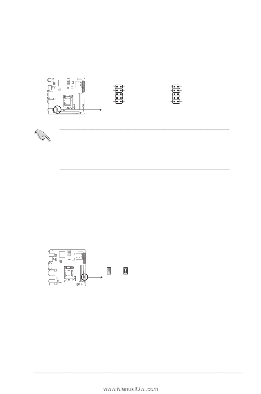
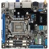
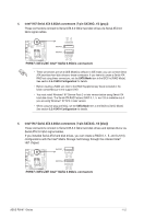
9. Front panel audio connector (10-1 pin AAFP) This connector is for a chassis-mounted front panel audio I/O module that supports either HD Audio or legacy AC`97 audio standard. Connect one end of the front panel audio I/O module cable to this connector. AAFP PIN 1 PORT1 L PORT1 R PORT2 R SENSE_SEND PORT2 L GND PRESENCE# SENSE1_RETUR SENSE2_RETUR PIN 1 MIC2 MICPWR Line out_R NC Line out_L AGND NC NC NC P8H67-I DELUXE HD-audio-compliant pin definition Legacy AC'97 compliant definition P8H67-I DELUXE Front panel audio connector • We recommend that you connect a high-definition front panel audio module to this connector to avail of the motherboard's high-definition audio capability. • If you want to connect a high-definition front panel audio module to this connector, set the Front Panel Type item in the BIOS setup to [HD]. If you want to connect an AC'97 front panel audio module to this connector, set the item to [AC97]. By default, this connector is set to [HD]. See section 2.5.6 Onboard Devices Configuration for details. 1.8 Onboard switches Onboard switches allow you to fine-tune performance when working on a bare or open-case system. This is ideal for overclockers and gamers who continually change settings to enhance system performance. 1. GPU Boost switch This switch allows you to enable or disable the GPU Boost function. GPU Boost P8H67-I DELUXE Enable Disable (Default) P8H67-I DELUXE GPU Boost switch 1-15 Chapter 1: Product introduction
-
 1
1 -
2
-
3
-
4
-
5
-
6
-
7
-
8
-
9
-
10
-
11
-
12
-
13
-
14
-
15
-
16
-
17
-
18
-
19
-
20
-
 21
21 -
 22
22 -
 23
23 -
 24
24 -
 25
25 -
 26
26 -
 27
27 -
 28
28 -
 29
29 -
 30
30 -
 31
31 -
32
-
33
-
34
-
35
-
36
-
37
-
38
-
39
-
40
-
41
-
42
-
43
-
44
-
45
-
46
-
47
-
48
-
49
-
50
-
51
-
52
-
53
-
54
-
55
-
56
-
57
-
58
-
59
 |
 |