Asus PP-DLW PP-DLW User Manual
Asus PP-DLW Manual
 |
View all Asus PP-DLW manuals
Add to My Manuals
Save this manual to your list of manuals |
Asus PP-DLW manual content summary:
- Asus PP-DLW | PP-DLW User Manual - Page 1
Motherboard PP-DLW User Guide - Asus PP-DLW | PP-DLW User Manual - Page 2
Product warranty or service will not be extended if: (1) the product is repaired, modified or altered, unless such repair, modification of alteration is authorized in writing by ASUS; or (2) the serial number of the product is defaced or missing. ASUS PROVIDES THIS MANUAL "AS IS" WITHOUT WARRANTY - Asus PP-DLW | PP-DLW User Manual - Page 3
guide viii ASUS contact information x PP-DLW specifications summary xi Chapter 1: Product introduction 1.1 Welcome 1-1 1.2 Package contents 1-1 1.3 Special features 1-2 1.3.1 Product highlights 1-2 1.3.2 Value-added solutions 1-4 Chapter 2: Hardware information 2.1 Motherboard installation - Asus PP-DLW | PP-DLW User Manual - Page 4
4-4 4.2.7 Pop-up window 4-4 4.3 Main menu 4-5 4.3.1 AMI BIOS 4-5 4.3.2 Processor 4-5 4.3.3 System Memory 4-5 4.3.4 System Time [xx:xx:xxxx 4-5 4.3.5 System Date System Health Configuration 4-15 4.5 PCI PnP menu 4-16 4.5.1 Plug & Play O/S [No 4-16 4.5.2 PCI Latency Timer [64 4-16 4.5.3 - Asus PP-DLW | PP-DLW User Manual - Page 5
PCI-64 Hub 2 Configuration 4-27 4.9 Power menu 4-28 4.10 Exit menu 4-30 Chapter 5: OS installation 5.1 Support CD contents 5-1 5.1.1 Drivers XP Professional 5-11 5.4.1 Intel 82540EM LAN driver installation 5-11 5.4.2 SoundMAX audio driver and appl. installation ..... 5-16 5.4.3 USB 2.0 driver - Asus PP-DLW | PP-DLW User Manual - Page 6
. This equipment generates, uses and can radiate radio frequency energy and, if not installed and used in accordance with manufacturer's instructions, may cause harmful interference to radio communications. However, there is no guarantee that interference will not occur in a particular installation - Asus PP-DLW | PP-DLW User Manual - Page 7
add a device. • Before connecting or removing signal cables from the motherboard, ensure that all power cables are unplugged. • Seek professional assistance before a stable surface. • If you encounter technical problems with the product, contact a qualified service technician or your retailer. vii - Asus PP-DLW | PP-DLW User Manual - Page 8
PP-DLW motherboard. How this guide is organized This manual contains the following parts: • Chapter 1: Product introduction This chapter describes the features of the PP-DLW motherboard. It includes brief descriptions of the special attributes of the motherboard and the new technology it supports - Asus PP-DLW | PP-DLW User Manual - Page 9
in this guide To make sure that you perform certain tasks properly, take note of the following symbols used throughout this manual. WARNING: ASUS Websites The ASUS websites worldwide provide updated information on ASUS hardware and software products. The ASUS websites are listed in the ASUS - Asus PP-DLW | PP-DLW User Manual - Page 10
CA 94560, USA General Fax: +1-510-608-4555 General Email: [email protected] Technical Support Support Fax: +1-510-608-4555 General Support: +1-502-933-8713 Web Site: www.asus.com Support Email: [email protected] ASUS COMPUTER GmbH (Germany and Austria) Address: Harkortstr. 25, 40880 Ratingen - Asus PP-DLW | PP-DLW User Manual - Page 11
PP-DLW specifications summary CPU Chipsets Front Side Bus (FSB) Memory Onboard LAN Onboard audio Expansion slots Rear panel I/O Internal connectors BIOS features Form Factor Support CD contents Support for dual Intel® Xeon™ processor with speeds up to 3.06 GHz On-die 256KB/512KB L2 cache Intel - Asus PP-DLW | PP-DLW User Manual - Page 12
xii - Asus PP-DLW | PP-DLW User Manual - Page 13
Chapter 1 This chapter describes the features of the PP-DLW motherboard. It includes brief explanations of the special attributes of the motherboard and the new technology it supports. Product introduction - Asus PP-DLW | PP-DLW User Manual - Page 14
Chapter summary 1.1 Welcome 1-1 1.2 Package contents 1-1 1.3 Special features 1-2 1.4 Motherboard overview 1-6 ASUS PP-DLW motherboard - Asus PP-DLW | PP-DLW User Manual - Page 15
the following items. ASUS PP-DLW motherboard Extended ATX form factor: 12 in x 10.5 in (30.5 cm x 26.7 cm) ASUS PP-DLW support CD I/O shield 80-conductor ribbon cable for UltraDMA100/66/33 IDE drives Ribbon cable for a 3.5-inch floppy drive Bag of extra jumper caps PP-DLW User Guide If any of the - Asus PP-DLW | PP-DLW User Manual - Page 16
The PP-DLW motherboard supports the Intel® Xeon processor via dual 604- DDR memory support Employing the Double Data Rate (DDR) memory technology, the PP-DLW motherboard supports up to 8GB of system memory using PC2100/1600 unbuffered/registered ECC/non-ECC DDR DIMMs. The ultra-fast 266MHz memory - Asus PP-DLW | PP-DLW User Manual - Page 17
and programmable gain blocks. ATA/100 IDE support The dual-channel bus master IDE connectors comply with the ATA/100 protocol and supports ATA/100, Multi-Word DMA Mode2, PIO modes 3 & 4 IDE devices such as ATAPI IDE CD-ROM, CD-R/RW, ZIP, and LS-120 drives. ASUS PP-DLW motherboard user guide 1-3 - Asus PP-DLW | PP-DLW User Manual - Page 18
ASUS components. Dual function support The motherboard includes Wake-On-LAN, Wake-On-Ring, and BIOS Wake-Up features. ACPI ready The Advanced Configuration power Interface (ACPI) provides more energy saving features for operating systems that support OS Direct Power Management (OSPM). Concurrent PCI - Asus PP-DLW | PP-DLW User Manual - Page 19
and power management for configuring and managing all system components, 32-bit device drivers, and installation procedures for Windows NT/2000/XP. Color-coded connectors and descriptive icons make identification easy as required by the PC '99 specification. ASUS PP-DLW motherboard user guide 1-5 - Asus PP-DLW | PP-DLW User Manual - Page 20
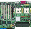
are the major components of the PP-DLW motherboard as pointed out in the picture on page 1-7. 1. ATX power connector 2. 604-pin CPU sockets 3. Intel® E7505 MCH (Placer) 4. 8-pin 12V SSI power connector 5. DDR DIMM sockets 6. AGP Pro 8X slot 7. Intel® P64H2 PCI-X hub 8. IDE connectors 9. Floppy disk - Asus PP-DLW | PP-DLW User Manual - Page 21
1 2 34 5 16 15 14 13 12 17 26 25 6 7 11 18 24 10 9 8 19 20 21 22 23 ASUS PP-DLW motherboard user guide 1-7 - Asus PP-DLW | PP-DLW User Manual - Page 22
dual-channel DDR SDRAM interface for up to 8GB system memory. 4 8-pin 12V SSI power connector. This 8-pin connector is for an ATX power supply. 5 DDR DIMM sockets. These four 184-pin DIMM sockets support up to 8GB system memory using unbuffered/registered ECC/non-ECC PC2100/1600 DDR DIMMs. 6 AGP - Asus PP-DLW | PP-DLW User Manual - Page 23
BIOS program. 12 PCI-X/PCI slots. One 64-bit/133MHz PCI-X slots, three 64-bit/ 100MHz PCI slot, and a 32-bit/33MHz PCI expansion slot support bus master PCI-X/PCI cards. 13 ASUS or a speaker. 22 Microphone port. This Mic (pink) port connects a microphone. ASUS PP-DLW motherboard user guide 1-9 - Asus PP-DLW | PP-DLW User Manual - Page 24
23 USB 2.0 ports 1 and 2. These 4-pin Universal Serial Bus (USB) ports are available for connecting USB 2.0 devices. 24 Serial ports. These 9-pin COM1/COM2 ports are for pointing devices or other serial devices. 25 USB 2.0 ports 3 and 4. These 4-pin Universal Serial Bus (USB) ports are available for - Asus PP-DLW | PP-DLW User Manual - Page 25
Chapter 2 This chapter describes the hardware setup procedures that you have to perform when installing system components. It includes details on the switch/jumper settings and connector locations on the motherboard. Hardware information - Asus PP-DLW | PP-DLW User Manual - Page 26
Chapter summary 2.1 Motherboard installation 2-1 2.2 Motherboard layout 2-2 2.3 Before you proceed 2-3 2.4 Central Processing Unit (CPU 2-4 2.5 System memory 2-8 2.6 Expansion slots 2-11 2.7 Jumpers 2-14 2.8 Connectors 2-18 ASUS PP-DLW motherboard - Asus PP-DLW | PP-DLW User Manual - Page 27
as indicated in the image below. 2.1.2 Screw holes Place 9 screws into the holes indicated by circles to secure the motherboard to the chassis. Do not overtighten the screws! Doing so may damage the motherboard. Place this side towards the rear of the chassis ASUS PP-DLW motherboard user guide 2-1 - Asus PP-DLW | PP-DLW User Manual - Page 28
-X2 (64-bit, 100MHz 3V) Bridge Hub J16 AUDIO_COM1 J18 PCI-X3 (64-bit, 100MHz 3V) LED4 ASUS ASIC with Hardware Monitor PCI-X4 (64-bit, 133MHz 3V) 4Mbit Flash BIOS J20 PCI1 (32-bit, 33MHz 5V) FAN5 GAME1 J26 J33 PP-DLW J25 J31 BATTERY1 Intel I/O Controller Hub (ICH4) BUZZ1 J21 J22 J23 J24 - Asus PP-DLW | PP-DLW User Manual - Page 29
with the component. 5. Before you install or remove any component, ensure that the ATX power supply is switched off or the power cord is detached from the power in any motherboard component. PP-DLW PP-DLW Onboard LED LED4 ON Standby Power OFF Powered Off ASUS PP-DLW motherboard user guide 2-3 - Asus PP-DLW | PP-DLW User Manual - Page 30
Overview The motherboard comes with dual surface mount instructions, and data transfer rate of up to 4.2GBps/3.2GBps. Xeon™ Processor PP-DLW PP-DLW Socket the socket may bend the pins and severely damage the CPU! The motherboard supports either one or two CPUs. If you are installing only one CPU - Asus PP-DLW | PP-DLW User Manual - Page 31
socket 2 first. Follow these steps to install a CPU. 1. Locate the 604-pin ZIF sockets on the motherboard. Unlock the socket by pressing the lever sideways, then lift it up to at least 115° angle. Make clicks on the side tab to indicate that it is locked. ASUS PP-DLW motherboard user guide 2-5 - Asus PP-DLW | PP-DLW User Manual - Page 32
2.4.3 Installing the CPU heatsink and fan The Intel® Xeon™ processors require specially designed heatsink and fan assembly to ensure optimum thermal condition and corner of the plastic retention base. (The retention base comes installed with the motherboard.) 2-6 Chapter 2: Hardware information - Asus PP-DLW | PP-DLW User Manual - Page 33
3. Use a small flat screw driver to attach the other end of the motherboard labeled FAN2 (for the CPU on socket 1) and FAN3 (for the CPU on socket 2). Don't forget to connect the CPU fan cable. Hardware monitoring problems may occur if you fail to plug the cable. ASUS PP-DLW motherboard user guide - Asus PP-DLW | PP-DLW User Manual - Page 34
The motherboard comes with four Double Data Rate (DDR) Dual Inline Memory Module (DIMM) sockets. These sockets support up to 8GB system memory using 184-pin unbuffered/registered ECC/non-ECC PC2100/1600 DIMMs with Serial Presence Detect (SPD). 80 Pins 104 Pins PP-DLW PP-DLW 184-Pin DDR DIMM - Asus PP-DLW | PP-DLW User Manual - Page 35
DIMMs in any configuration. Table 1 Recommended memory configurations Mode Single-channel Dual-channel DDR1 (1) Module A (2) - (3) Memory frequency/CPU FSB synchronization CPU FSB 533 MHz 400 MHz DDR DIMM Type PC2100 PC1600 Memory Frequency 266 MHz 200 MHz ASUS PP-DLW motherboard user guide - Asus PP-DLW | PP-DLW User Manual - Page 36
components. Failure to do so may cause severe damage to both the motherboard and the components. Follow these steps to install a DIMM. 1. Unlock outward to unlock the DIMM. 2. Remove the DIMM from the socket. Support the DIMM lightly with your fingers when pressing the retaining clips. The DIMM - Asus PP-DLW | PP-DLW User Manual - Page 37
and the expansion cards that they support. Make sure to unplug the power BIOS settings, if any. See Chapter 4 for information on BIOS setup. 2. Assign an IRQ to the card. Refer to the tables on the next page. 3. Install the software drivers for the expansion card. ASUS PP-DLW motherboard user guide - Asus PP-DLW | PP-DLW User Manual - Page 38
PCI slot 1 PIRQF AGP Pro slot PIRQA Onboard 82540EM controller PIRQD PCI INTB PBIRQ1 PBIRQ5 PBIRQ9 PAIRQ1 PIRQG PIRQB - PCI INTC PBIRQ2 PBIRQ6 PBIRQ10 PAIRQ2 PIRQH - - PCI INTD PBIRQ3 PBIRQ7 PBIRQ11 PAIRQ3 PIRQE - - When using PCI cards on shared slots, ensure that the drivers support - Asus PP-DLW | PP-DLW User Manual - Page 39
. The AGP PRO slot comes with a warning label and a safety tab. Remove the label and tab ONLY if you are installing an AGP PRO card. Use a pointed object, such as a pen tip, to dislodge the tab. Keyed for 1.5V PP-DLW PP-DLW Accelerated Graphics Port (AGP) ASUS PP-DLW motherboard user guide 2-13 - Asus PP-DLW | PP-DLW User Manual - Page 40
operation. 1. JumperFree™ setting (J22) This jumper allows you to enable or disable the JumperFree™ mode. J22 12 23 Jumper Mode PP-DLW PP-DLW JumperFree™ Mode Setting Jumper Free (Default) 2. CPU external frequency selection (J12) This jumper allows you to select your desired CPU external - Asus PP-DLW | PP-DLW User Manual - Page 41
. PP-DLW PP-DLW LAN Setting J14 12 23 Enable (Default) Disable 4. PCI-X slot setting (J15) This jumper allows you to select your desired bus speed for PCI-X1 to PCI-X3 slots. PP-DLW PP-DLW PCI Slot Setting J33 1 2 PCI-X 100MHz (Default) 2 3 PCI-X 66MHz ASUS PP-DLW motherboard user guide - Asus PP-DLW | PP-DLW User Manual - Page 42
computer when you press a key on the keyboard. This feature requires an ATX power supply that can supply at least 1A on the +5VSB lead, and a corresponding setting in the BIOS. J1 12 23 +5V (Default) +5VSB PP-DLW PP-DLW Keyboard Power Setting 6. USB device wake-up (J28, J29, J20) Set these - Asus PP-DLW | PP-DLW User Manual - Page 43
the CMOS memory of date, BIOS setup to re-enter data. Except when clearing the RTC RAM, never remove the cap on CLRTC jumper default position. Removing the cap will cause system boot failure! PP-DLW PP-DLW Clear RTC RAM J21 12 23 Normal (Default) Clear CMOS ASUS PP-DLW motherboard user guide - Asus PP-DLW | PP-DLW User Manual - Page 44
to light up. PP-DLW PP-DLW IDE Activity LED J24 +- TIP: If the case-mounted LED does not light, try reversing the 2-pin plug. 2. Floppy disk drive connector (34-1 pin FLOPPY) This connector supports the provided floppy drive ribbon cable. After connecting one end to the motherboard, connect the - Asus PP-DLW | PP-DLW User Manual - Page 45
PP-DLW PP-DLW IDE Connectors NOTE: Orient the red markings (usually zigzag) on the IDE ribbon cable to PIN 1. For UltraDMA/100/66 IDE devices, use an 80-conductor IDE cable. The UltraDMA/66 cable included in the motherboard package also supports UltraDMA/100. ASUS PP-DLW motherboard user guide - Asus PP-DLW | PP-DLW User Manual - Page 46
to use the chassis intrusion detection feature, remove the jumper cap from the pins. J23 +5Volt (Power Supply Stand By) Chassis Signal Ground PP-DLW PP-DLW Chassis Open Alarm Lead 5. SMBus connector (6-1 pin J16) This connector allows you to connect SMBus (System Management Bus) devices. Devices - Asus PP-DLW | PP-DLW User Manual - Page 47
+12 Volts +5 Volts +12 Volts +5 Volts +3 Volts Ground PP-DLW PP-DLW ATX Power Connector GND 12V GND 12V GND 12V GND 12V For Power devices. PP-DLW PP-DLW Intel Panel Connector J5 BOUT_L BOUT_R +5VA AGND_A LOUT_L NC LOUT_R MICPWR MIC2 1 ASUS PP-DLW motherboard user guide 2-21 - Asus PP-DLW | PP-DLW User Manual - Page 48
air flow within the system may damage the motherboard components. These are not jumpers! DO NOT place jumper caps on the fan connectors! FAN1 Rotation +12V GND FAN3 FAN2 Rotation +12V GND Rotation +12V GND FAN4 GND +12V Rotation FAN5 PP-DLW PP-DLW 12-Volt Cooling Fan Power Rotation +12V GND - Asus PP-DLW | PP-DLW User Manual - Page 49
five pins as shown in Back View and connect a ribbon cable from the module to the motherboard SIR connector according to the pin definitions. J26 Front View Back View IRTX GND IRRX +5V 1 PP-DLW PP-DLW Infrared Module Connector ASUS PP-DLW motherboard user guide IRTX GND IRRX +5V (NC) 2-23 - Asus PP-DLW | PP-DLW User Manual - Page 50
bus that allows multiple chips to connect to the same bus and enable each one to act as a master by initiating data transfer. PP-DLW PP-DLW SMBus Connector J16 1 FLOATING SMBCLK Ground SMBDATA +5V 13. Internal audio connectors (4-pin AUDIO_COM1, AUDIO_COM2) These connectors allow you to receive - Asus PP-DLW | PP-DLW User Manual - Page 51
Speaker Power LED Connector +5VSB PLED Keylock Ground +5V Ground Ground Speaker +5 V MLED ExtSMI# Ground PWR Ground Reset Ground PP-DLW PP-DLW System Panel Connectors Message LED SMI Lead Reset SW ATX Power Switch* * Requires an ATX power supply. ASUS PP-DLW motherboard user guide 2-25 - Asus PP-DLW | PP-DLW User Manual - Page 52
ACPI OS and driver support. • System Warning Speaker Lead (4-pin SPEAKER) This 4-pin connector is for a chassis-mounted speaker. • ATX Power Switch / This lead connects to the case-mounted suspend switch, and allows you to manually place the system into "Suspend Mode" or "Green Mode" where system - Asus PP-DLW | PP-DLW User Manual - Page 53
Chapter 3 This chapter describes the power up sequence and gives information on the BIOS beep codes. Powering up - Asus PP-DLW | PP-DLW User Manual - Page 54
Chapter summary 3.1 Starting up for the first time 3-1 3.2 Powering off the computer 3-1 ASUS PP-DLW motherboard - Asus PP-DLW | PP-DLW User Manual - Page 55
your retailer for assistance. 7. At power on, hold down to enter BIOS Setup. Follow the instructions in Chapter 4. 3.2 Powering off the computer You must first exit the operating computer" does not appear when shutting down with ATX power supplies. ASUS PP-DLW motherboard user guide 3-1 - Asus PP-DLW | PP-DLW User Manual - Page 56
3-2 Chapter 3: Powering up - Asus PP-DLW | PP-DLW User Manual - Page 57
Chapter 4 This chapter tells how to change system settings through the BIOS Setup menus. Detailed descriptions of the BIOS parameters are also provided. BIOS setup - Asus PP-DLW | PP-DLW User Manual - Page 58
Chapter summary 4.1 Managing and updating your BIOS 4-1 4.2 BIOS Setup program 4-5 4.3 Main menu 4-8 4.4 Advanced menu 4-9 4.5 PCI PnP menu 4-19 4.6 Boot menu 4-22 4.7 Security menu 4-27 4.8 Chipset menu 4-28 4.9 Power menu 4-33 4.10 Exit menu 4-34 ASUS PP-DLW motherboard - Asus PP-DLW | PP-DLW User Manual - Page 59
current BIOS on the motherboard. Visit the ASUS website (www.asus.com) to obtain BIOS updates for this motherboard. 4. Press Enter. The screen displays the status of the update and goes back to the DOS prompt when done. 5. Boot the system with the new BIOS. ASUS PP-DLW motherboard user guide 4-1 - Asus PP-DLW | PP-DLW User Manual - Page 60
Setup program This motherboard supports a programmable firmware hub (FWH) that you can update using the provided utility described in section "4.1 Managing and updating your BIOS." Use the BIOS Setup program when you are installing a motherboard, reconfiguring your system, or prompted to "Run Setup - Asus PP-DLW | PP-DLW User Manual - Page 61
4.2.1 BIOS menu screen Menu bar General help Menu system configuration For changing the advanced system settings For changing the PCI/PnP settings For changing the system boot configuration For changing the keyboard until the desired item is highlighted. ASUS PP-DLW motherboard user guide 4-3 - Asus PP-DLW | PP-DLW User Manual - Page 62
item in the menu, then press Enter to display a pop-up window with the configuration options for that item. 4-4 Scroll bar Pop-up window Chapter 4: BIOS Setup - Asus PP-DLW | PP-DLW User Manual - Page 63
CPU specification. 4.3.3 System Memory This item displays the auto-detected system memory installed. 4.3.4 System Time [xx:xx:xxxx] This item allows you to set the system time. 4.3.5 System Date [Day xx/xx/xxxx] This item allows you to set the system date. ASUS PP-DLW motherboard user guide 4-5 - Asus PP-DLW | PP-DLW User Manual - Page 64
Configuration The items in this menu allow you to change CPU-related settings. Select the item then press Enter to display the sub-menu. 4-6 Chapter 4: BIOS Setup - Asus PP-DLW | PP-DLW User Manual - Page 65
Status, and Ratio Actual Value are auto-detected by BIOS and are not user-configurable. Ratio CMOS Setting [8] PCI IDE Controller [Both] This item allows you to enable or disable the IDE controller. Configuration options: [Disabled] [Primary] [Secondary] [Both] ASUS PP-DLW motherboard user guide - Asus PP-DLW | PP-DLW User Manual - Page 66
Block Mode, PIO Mode, Async DMA, Ultra DMA, and S.M.A.R.T. are autodetected by BIOS and are not user-configurable.These items show N/A if no IDE device is to the device occurs multiple sectors at a time if the device supports multi-sector transfer feature. When set to Disabled, the data transfer - Asus PP-DLW | PP-DLW User Manual - Page 67
disables device write protection. This will be effective only if the device is accessed through BIOS. Configuration options: [Disabled] [Enabled] IDE Detect Time Out (Sec) [35] 80-pin ATA/ATAPI cable. Configuration options: [Host & Device] [Host] [Device] ASUS PP-DLW motherboard user guide 4-9 - Asus PP-DLW | PP-DLW User Manual - Page 68
The items in this menu allow you to configure the Super I/O chipset. Select an item then press Enter to display the configuration options. 4-10 Chapter 4: BIOS Setup - Asus PP-DLW | PP-DLW User Manual - Page 69
] EPP Version [1.9] Allows selection of the Parallel Port EPP version. This item appears only when the Parallel Port Mode is set to EPP. Configuration options: [1.9] [1.7] ASUS PP-DLW motherboard user guide 4-11 - Asus PP-DLW | PP-DLW User Manual - Page 70
to display the configuration options. For other items, a sub-menu appears when you press Enter. ACPI Aware O/S [Yes] Allows you to enable or disable ACPI support for your operating system. Select No if your operating system does not - Asus PP-DLW | PP-DLW User Manual - Page 71
ACPI Configuration Allows you to change the advanced ACPI settings. BIOS -> AML ACPI Table [Enabled] Allows you to enable or disable the inclusion of the BIOS -> AML exchange pointer to (X)RSDT pointer list. Configuration options: [Disabled] [Enabled] ASUS PP-DLW motherboard user guide 4-13 - Asus PP-DLW | PP-DLW User Manual - Page 72
support if no USB devices are connected. Configuration options: [Disabled] [Enabled] [Auto] USB 2.0 Controller Mode [HiSpeed] Allows you to configure the USB 2.0 controller in HiSpeed (480 Mbps) or Full Speed (12 Mbps). Configuration options: [HiSpeed ] [Full Speed] 4-14 Chapter 4: BIOS Setup - Asus PP-DLW | PP-DLW User Manual - Page 73
enabled, the items in the menu displays the autodetected fan speeds, system temperatures, and output voltages. When disabled, the items show [N/A]. Configuration options: [Disabled] [Enabled] ASUS PP-DLW motherboard user guide 4-15 - Asus PP-DLW | PP-DLW User Manual - Page 74
devices, and enabling or disabling the PCI device option ROM for shadow memory. Take caution when changing the settings of the PCI PnP menu items. Incorrect field values may cause the system to malfunction. 4.5.1 Plug & Play O/S [No] When set to [No], BIOS configures all the devices in the system - Asus PP-DLW | PP-DLW User Manual - Page 75
option ROM to shadow memory. Configuration options: [Disabled] [Enabled] 4.5.5 Onboard LAN Option ROM Keep [Enabled] This item allows you to enable or disable copying the onboard LAN option ROM to shadow memory. Configuration options: [Disabled] [Enabled] ASUS PP-DLW motherboard user guide 4-17 - Asus PP-DLW | PP-DLW User Manual - Page 76
4.6.1 Boot Settings Configuration Quick Boot [Enabled] Enabling this item allows BIOS to skip some power on self tests (POST) while booting to decrease the time needed to boot the system. When set to [Disabled], BIOS performs all the POST items. Configuration options: [Disabled] [Enabled] Quiet - Asus PP-DLW | PP-DLW User Manual - Page 77
for the NumLock. Configuration options: [Off] [On] PS/2 Mouse Support [Enabled] Allows you to enable or disable support fr PS/2 mouse. Configuration options: [Disabled] [enabled] Typematic to trap Interrupt 19. Configuration options: [Disabled] [Enabled] ASUS PP-DLW motherboard user guide 4-19 - Asus PP-DLW | PP-DLW User Manual - Page 78
device items that appear on the screen depends on the the number of devices installed in the system. Configuration options: [xxxxx Drive] [Disabled] 4-20 Chapter 4: BIOS Setup - Asus PP-DLW | PP-DLW User Manual - Page 79
number of device items that appear on the screen depends on the the number of devices installed in the system. Configuration options: [xxxxx Drive] [Disabled] ASUS PP-DLW motherboard user guide 4-21 - Asus PP-DLW | PP-DLW User Manual - Page 80
as in setting a user password. To clear the supervisor password, select the Change Supervisor Password then press Enter. The message "Password Uninstalled" appears. 4-22 Chapter 4: BIOS Setup - Asus PP-DLW | PP-DLW User Manual - Page 81
user password, follow the same steps as in setting a user password. 4.7.4 Clear User Password Select this item if you wish to clear the user password. ASUS PP-DLW motherboard user guide 4-23 - Asus PP-DLW | PP-DLW User Manual - Page 82
checks for user password when accessing the Setup utility. When set to [Always], BIOS checks for user password both when accessing Setup and booting the system. Configuration options: [Setup] [ value of this item returns to Ignore. Configuration options: [Ignore] [Clear] 4-24 Chapter 4: BIOS Setup - Asus PP-DLW | PP-DLW User Manual - Page 83
field values may cause the system to malfunction. 4.8.1 Configure Advanced Settings for NorthBridge Graphics Aperture Size [64MB] Allows you to select the size of the AGP aperture. Configuration options: [4MB] [8MB] [16MB] [32MB] [64MB] [128MB] [256MB] ASUS PP-DLW motherboard user guide 4-25 - Asus PP-DLW | PP-DLW User Manual - Page 84
controller 1. Configuration options: [Disabled] [Enabled] ICH4 Dev29 Func1, USB#2 [Enabled] Allows you to enable or disable the USB controller 2. Configuration options: [Disabled] [Enabled] 4-26 Chapter 4: BIOS Setup - Asus PP-DLW | PP-DLW User Manual - Page 85
Frequency [Auto] Allows selection of maximum PCI bus speed to be programmed. The default setting is Auto so that the bus speed is decided based on the capabilities of te device on that bus. Configuration options: [33 Mhz] [66 MHz] [100 MHz] [133 MHz] [Auto] ASUS PP-DLW motherboard user guide 4-27 - Asus PP-DLW | PP-DLW User Manual - Page 86
is set to Enabled. Configuration options: [Disabled] [1 Min] [2 Min] [4 Min] [8 Min] [10 Min] [20 Min] [30 Min] [40 Min] [50 Min] [60 Min] 4-28 Chapter 4: BIOS Setup - Asus PP-DLW | PP-DLW User Manual - Page 87
to Enabled, the items RTC Alarm Date, RTC Alarm Hour, RTC Alarm Minute, and RTC Alarm Second appear with set values. Configuration options: [Disabled] [Enabled] ASUS PP-DLW motherboard user guide 4-29 - Asus PP-DLW | PP-DLW User Manual - Page 88
4.10 Exit menu The Exit menu items allow you to load the optimal or failsafe default values for the BIOS items, and save or discard your changes to the BIOS items. 4.10.1 Save Changes and Exit Saves the changes that you made before exiting Setup. 4.10.2 Discard Changes and Exit Exits setup without - Asus PP-DLW | PP-DLW User Manual - Page 89
Chapter 5 This chapter tells how to install LAN, USB, and audio drivers under various operating systems (OS). Driver installation - Asus PP-DLW | PP-DLW User Manual - Page 90
® Windows® NT Server 4.0 5-3 5.3 Microsoft® Windows® 2000 Server 5-6 5.4 Microsoft®Windows® XP Professional ...... 5-11 5.5 Novell® NetWare® Server 5-22 5.6 SUN Solaris 7 Server 5-24 5.7 SCO Open Server 5.0.x 5-24 5.8 SCO UnixWare Server 5-25 5.9 Linux RedHat 7.x 5-26 ASUS PP-DLW motherboard - Asus PP-DLW | PP-DLW User Manual - Page 91
displays the drivers available for the onboard devices. Follow the installation wizards or find additional instructions as text files in each of the driver folders. 5.1.2 Management Sofware This screen displays the ASUS proprietary server management software. ASUS PP-DLW motherboard user guide 5-1 - Asus PP-DLW | PP-DLW User Manual - Page 92
5.1.3 Utilities This screen displays the available system utilities that you can install. 5.1.4 Contact This screen displays the ASUS worldwide contact information. 5-2 Chapter 5: Driver installation - Asus PP-DLW | PP-DLW User Manual - Page 93
disk drive when prompted. 4. Proceed to the next section to install the LAN drivers from the driver disk that you created. B. New System Installation 1. When the Installing Windows NT Networking screen appears, press Next to display the following screen. ASUS PP-DLW motherboard user guide 5-3 - Asus PP-DLW | PP-DLW User Manual - Page 94
screen that appears, click the button Select from list... to dispaly the following. 4. Insert the LAN driver disk that you created, then click Have Disk... 5. Type A:\ in the dialog box that appears, , then click OK. Follow the succeeding screen instructions. 5-4 Chapter 5: Driver installation - Asus PP-DLW | PP-DLW User Manual - Page 95
driver disk that you created from the support CD. Refer to section "A. Preparing the Intel 82540EM LAN Driver Disk" if you have not yet created the LAN driver disk. 5. Follow steps 4 to 8 in section "B. New System Installation" to install the required LAN drivers. ASUS PP-DLW motherboard user guide - Asus PP-DLW | PP-DLW User Manual - Page 96
disk into the floppy disk drive when prompted. 4. Follow the screen instructions to complete the process. B. Update driver on an existing system installation You may update the LAN driver directly from the support CD. 1. Insert the support CD into the CD-ROM drive. On the screen that appears, click - Asus PP-DLW | PP-DLW User Manual - Page 97
When done, your Computer Management window shows the installed LAN adapter. 4. Highlight the Intel(R) PRO-1000 LAN Driver, click the right mouse button, and select Properties to display the following. ASUS PP-DLW motherboard user guide 5-7 - Asus PP-DLW | PP-DLW User Manual - Page 98
Select the Driver tab and click on Update Drivers. 7. Click Next. Select Display a list of the known drivers for this device ... 8. Select Network adapters under Hardware Type, and click Next. 9. Click Have Disk..., then insert the LAN driver disk. 10. Follow the succeeding instructions to complete - Asus PP-DLW | PP-DLW User Manual - Page 99
drivers and applications in the following path: \Drivers\SoundMAX\Win_2K\ 3. Follow the screen instructions to install the SoundMAX wizard. 4. When prompted, select the option Yes, I want to restart my computer now, then click Finish to complete the installation. ASUS PP-DLW motherboard user guide - Asus PP-DLW | PP-DLW User Manual - Page 100
a device driver, select Intel PCI to USB Enhanced Host Controller, then click Next. 5. Follow the succeeding instructions to complete the installation. 5.3.4 Enabling ATA100 Feature in Windows® 2000 To enable the ATA100 feature under Windows 2000, you need to upgrade to Windows 2000 Service Pack - Asus PP-DLW | PP-DLW User Manual - Page 101
the Intel 82540EM LAN driver disk Prepare one blank formatted high density floppy disk before proceeding. 1. Insert the support CD into the CD-ROM drive. 2. On the screen that appears, select Create Install Disk. The following information window appears. ASUS PP-DLW motherboard user guide 5-11 - Asus PP-DLW | PP-DLW User Manual - Page 102
3. The next screen allows you to select an operating system to install the driver. Select Windows XP/64. 4. Select A:/ for the destination drive, then click on Create Disk. 5. Follow the succeeding installation instructions. 6. When prompted, click Finish to complete the process. 5-12 Chapter 5: - Asus PP-DLW | PP-DLW User Manual - Page 103
the support CD into the CD-ROM drive. On the screen that appears, click on Intel PRO/1000 LAN Driver, then on the item Install Drivers and Utilities. 2. The following screen appears allowing you to install the Intel(R) PRO Intelligent Installer. Click Next. ASUS PP-DLW motherboard user guide 5-13 - Asus PP-DLW | PP-DLW User Manual - Page 104
3. The following screen prompts you to select the Setup type. Select Custom, then click Next. 4. On the next screen, select Drivers for wired Ethernet adapters, then click Next. 5. Click Finish when done installing the wizard. 5-14 Chapter 5: Driver installation - Asus PP-DLW | PP-DLW User Manual - Page 105
6. The following screen displays the network components that you cna install. Select Intel(R) PRO/1000 MT Network Connection, then click OK. 7. Follow the succeeding screen instructions to complete the installation. ASUS PP-DLW motherboard user guide 5-15 - Asus PP-DLW | PP-DLW User Manual - Page 106
controller under Windows XP: 1. Insert the support CD into your CD-ROM drive. When Autorun in enabled in your computer, the Drivers menu automatically appears. 2. Click on the SoundMAX Audio Driver and Application item to start the audio installation. 3. Follow the screen instructions to install the - Asus PP-DLW | PP-DLW User Manual - Page 107
for the MIDI. Click the arrow under the Synthesizer Default Set to display a list of options, and choose your desired setting. 6. Click OK when done. ASUS PP-DLW motherboard user guide 5-17 - Asus PP-DLW | PP-DLW User Manual - Page 108
5.4.3 USB 2.0 driver installation To update the USB 2.0 driver under Windows XP: 1. Open the Device Manager, select Universal Serial Bus controllers. 2. Right-click on the item to display the Universal Serial Bus (USB) Controller Properties window. 5-18 Chapter 5: Driver installation - Asus PP-DLW | PP-DLW User Manual - Page 109
3. In the following screen, select Install from a list or specific location (Advanced), then click Next. 4. For Hardware Type, choose Universal Serial Bus Controllers. Click Next. ASUS PP-DLW motherboard user guide 5-19 - Asus PP-DLW | PP-DLW User Manual - Page 110
5. When prompted to select the device driver to install, select Standard Universal PCI to USB Host Controller, then click Next. 6. Locate the file usb2x from the from your specified location. Click Open. 5-20 Chapter 5: Driver installation - Asus PP-DLW | PP-DLW User Manual - Page 111
7. Select the model of the device that you wish to install, then click Have Disk. 8. Follow the succeeding screen instructions 9. When prompted, click Finish to complete the installation. ASUS PP-DLW motherboard user guide 5-21 - Asus PP-DLW | PP-DLW User Manual - Page 112
file is located here: \Drivers\Lan\makedisk\makenw.bat 2. Use the manual to create driver disk. If you need to use a floppy disk to install the onboard Intel 82540EM network adapter drivers, use the MAKEDISK.BAT utility located at \Drivers\LAN\MAKEDISK in the support CD. MAKEDISK [operating system - Asus PP-DLW | PP-DLW User Manual - Page 113
.2. If your workstation needs to use the 802.3 frame type, see the section later in this document about using multiple frame types on one adapter. ASUS PP-DLW motherboard user guide 5-23 - Asus PP-DLW | PP-DLW User Manual - Page 114
during installation. User doesn't need to load or modify the network driver for the onboard LAN device. You can find the Intel 82540EM Network driver from support CD at: \Drivers\Lan\UNIX\SCO5 Instructions for Installing the eeE Driver for SCO OpenServer 1. Copy the eee.vol file to any directory - Asus PP-DLW | PP-DLW User Manual - Page 115
the system. If you require Hot Plug PCI capabilities, the DDI 8 eeE8 driver must be used. The DDI 8 driver is supported on UnixWare 7.1.0 and later versions. For more information about Hot Plug PCI capabilities please refer to SCO UnixWare 7 documentation. ASUS PP-DLW motherboard user guide 5-25 - Asus PP-DLW | PP-DLW User Manual - Page 116
5.9 Linux RedHat 7.x 5.9.1 Intel 82540EM LAN Driver Installation Linux RedHat 7.x system can automatically recognize Intel 82540EM network controller during installation. You don't need to load or modify the network driver for the onboard LAN device. 5-26 Chapter 5: Driver installation
-
 1
1 -
 2
2 -
 3
3 -
 4
4 -
 5
5 -
 6
6 -
 7
7 -
8
-
9
-
10
-
11
-
12
-
13
-
14
-
15
-
16
-
17
-
18
-
19
-
20
-
21
-
22
-
23
-
24
-
25
-
26
-
27
-
28
-
29
-
30
-
31
-
32
-
33
-
34
-
35
-
36
-
37
-
38
-
39
-
40
-
41
-
42
-
43
-
44
-
45
-
46
-
47
-
48
-
49
-
50
-
51
-
52
-
53
-
54
-
55
-
56
-
57
-
58
-
59
-
60
-
61
-
62
-
63
-
64
-
65
-
66
-
67
-
68
-
69
-
70
-
71
-
72
-
73
-
74
-
75
-
76
-
77
-
78
-
79
-
80
-
81
-
82
-
83
-
84
-
85
-
86
-
87
-
88
-
89
-
90
-
91
-
92
-
93
-
94
-
95
-
96
-
97
-
98
-
99
-
100
-
101
-
102
-
103
-
104
-
105
-
106
-
107
-
108
-
109
-
110
-
111
-
112
-
113
-
114
-
115
-
116
 |
 |

Motherboard
PP-DLW
User Guide