Asus PP-DLW PP-DLW User Manual - Page 47
ASUS PP-DLW motherboard user guide, ATX power connectors 24/20-pin EATXPWR, 8-pin CON12V, Front
 |
View all Asus PP-DLW manuals
Add to My Manuals
Save this manual to your list of manuals |
Page 47 highlights
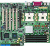
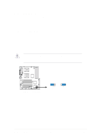
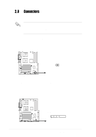
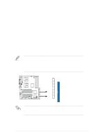
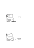
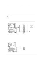
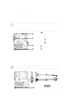
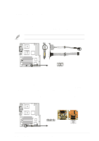
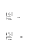
6. ATX power connectors (24/20-pin EATXPWR, 8-pin CON12V) These connectors connect to an ATX 12V power supply. The plugs from the power supply are designed to fit these connectors in only one orientation. Find the proper orientation and push down firmly until the connectors completely fit. In addition to the 24/20-pin EATXPWR connector, this motherboard requires that you connect the 8-pin +12V power plug to the CON12V connector to provide sufficient power to the CPU. Make sure that your ATX 12V power supply can provide 20A on the +12V lead and at least 1A on the +5-volt standby lead (+5VSB). The minimum recommended wattage is 300W for a fully configured system. The system may become unstable and may experience difficulty powering up if the power supply is inadequate. 24-pin Power Connector 1 +3 Volts +3 Volts +3 Volts -12 Volts Ground Ground +5 Volts PSON# Ground Ground +5 Volts Ground Ground Power OK Ground -5 Volts +5V Standby +5 Volts +12 Volts +5 Volts +12 Volts +5 Volts +3 Volts Ground PP-DLW PP-DLW ATX Power Connector GND 12V GND 12V GND 12V GND 12V For Power Supply with 20-pin Power Connector 8-pin 7. Front panel audio connector (10-1 pin J5) This is an interface for the Intel front panel audio cable that allow convenient connection and control of audio devices. PP-DLW PP-DLW Intel Panel Connector J5 BOUT_L BOUT_R +5VA AGND_A LOUT_L NC LOUT_R MICPWR MIC2 1 ASUS PP-DLW motherboard user guide 2-21
-
 1
1 -
2
-
3
-
4
-
5
-
6
-
7
-
8
-
9
-
10
-
11
-
12
-
13
-
14
-
15
-
16
-
17
-
18
-
19
-
20
-
21
-
22
-
23
-
24
-
25
-
26
-
27
-
28
-
29
-
30
-
31
-
32
-
33
-
34
-
35
-
36
-
37
-
38
-
39
-
40
-
41
-
 42
42 -
 43
43 -
 44
44 -
 45
45 -
 46
46 -
 47
47 -
 48
48 -
 49
49 -
 50
50 -
 51
51 -
 52
52 -
53
-
54
-
55
-
56
-
57
-
58
-
59
-
60
-
61
-
62
-
63
-
64
-
65
-
66
-
67
-
68
-
69
-
70
-
71
-
72
-
73
-
74
-
75
-
76
-
77
-
78
-
79
-
80
-
81
-
82
-
83
-
84
-
85
-
86
-
87
-
88
-
89
-
90
-
91
-
92
-
93
-
94
-
95
-
96
-
97
-
98
-
99
-
100
-
101
-
102
-
103
-
104
-
105
-
106
-
107
-
108
-
109
-
110
-
111
-
112
-
113
-
114
-
115
-
116
 |
 |
