Asus PRIME B250-PLUS PRIME B250-PLUS USER S MANUAL ENGLISH - Page 12
System panel connector 20-5 pin F_PANEL, Clear RTC RAM 2-pin CLRTC, To erase the RTC RAM - compatibility
 |
View all Asus PRIME B250-PLUS manuals
Add to My Manuals
Save this manual to your list of manuals |
Page 12 highlights
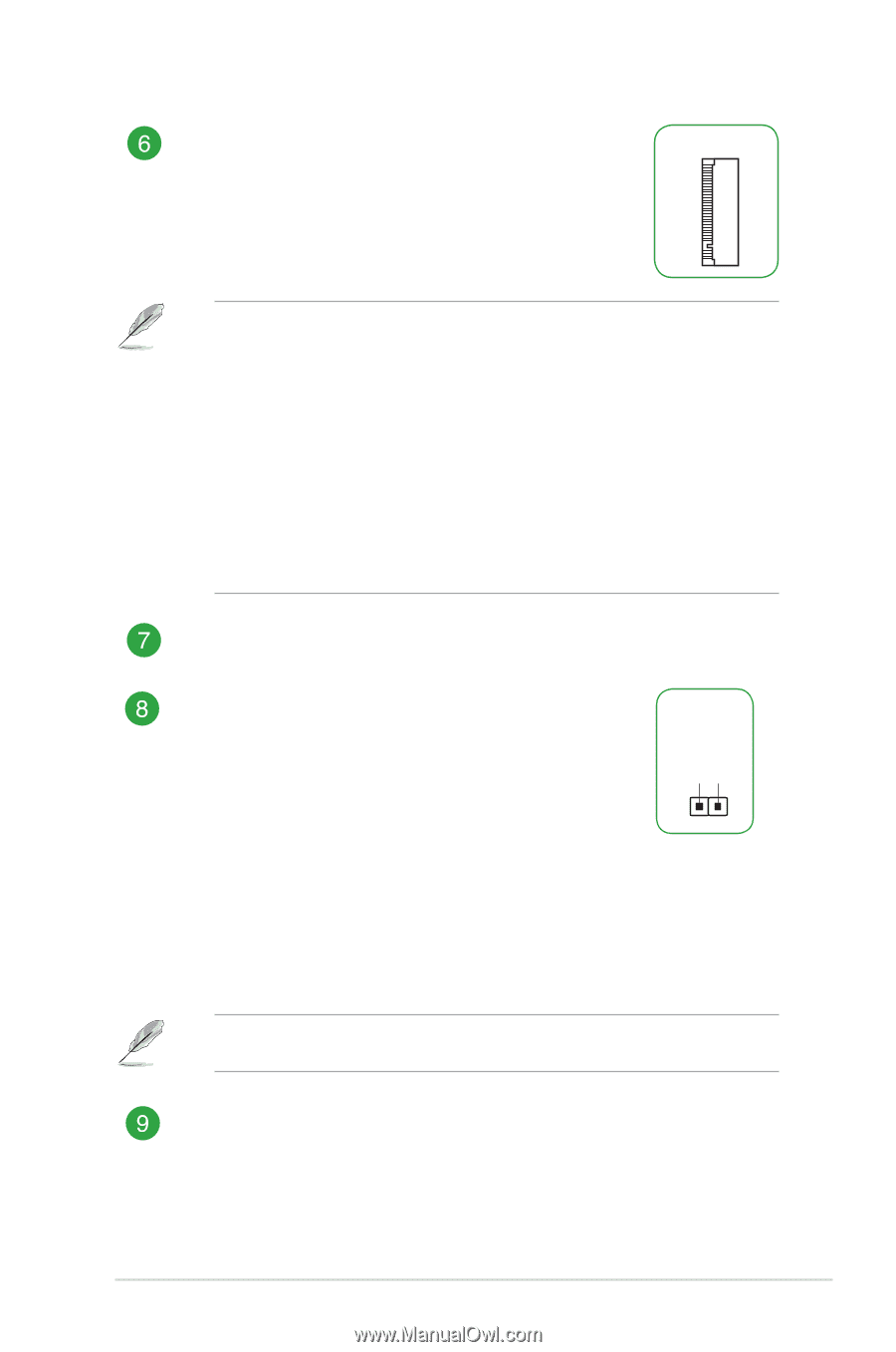
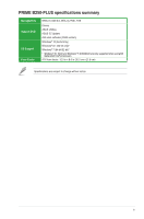
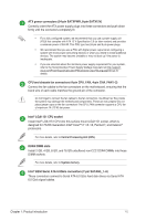
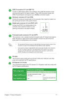
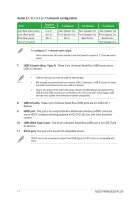
M.2 socket 3 These sockets allow you to install M.2 (NGFF) SSD modules. M.2(SOCKET3) • These M.2 sockets support M Key and 2242/2260/2280 storage devices. • The M.2_1 socket supports data transfer speed up to 16Gb/s. • The M.2_2 socket supports data transfer speed up to 32Gb/s. • Only M.2_2 socket can support Intel® Optane™ Memory. Intel® Optane™ Technology is only supported when using 7th Generation Intel® processors. Before using Intel® Optane™ memory modules, ensure that you have updated your motherboard drivers and BIOS to the latest version from ASUS support website. • When an M.2 device in PCIe mode is installed onto M.2_1, PCIe x16_2 slot only runs at x1 mode and SATA6G_1 port is enabled. • When an M.2 device in SATA mode is installed onto M.2_1, the M.2 device uses the SATA6G_1 bandwidth. SATA6G_1 port is disabled. System panel connector (20-5 pin F_PANEL) This connector supports several chassis-mounted functions. Clear RTC RAM (2-pin CLRTC) This header allows you to clear the CMOS RTC RAM data of the system setup information such as date, time, and system passwords. To erase the RTC RAM: 1. Turn OFF the computer and unplug the power cord. 2. Use a metal object such as a screwdriver to short the two pins. 3. Plug the power cord and turn ON the computer. 4. Hold down the key during the boot process and enter BIOS setup to re-enter data. +3V_BAT GND CLRTC PIN 1 If the steps above do not help, remove the onboard battery and short the two pins again to clear the CMOS RTC RAM data. After clearing the CMOS, reinstall the battery. USB 3.0 connectors (20-1 pin USB3_12) Connect a USB 3.0 module to any this connector for additional USB 3.0 front or rear panel ports. This connector complies with USB 3.0 specifications and provide faster data transfer speeds of up to 5 Gbps, faster charging time for USBchargeable devices, optimized power efficiency, and backward compatibility with USB 2.0. 1-3 ASUS PRIME B250-PLUS
-
 1
1 -
2
-
3
-
4
-
5
-
6
-
 7
7 -
 8
8 -
 9
9 -
 10
10 -
 11
11 -
 12
12 -
 13
13 -
 14
14 -
 15
15 -
 16
16 -
 17
17 -
18
-
19
-
20
-
21
-
22
-
23
-
24
-
25
-
26
-
27
-
28
 |
 |