Asus PRIME B365M-A Users Manual English - Page 11
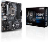
DDR4 DIMM slots, LGA1151 CPU socket
 |
View all Asus PRIME B365M-A manuals
Add to My Manuals
Save this manual to your list of manuals |
Page 11 highlights
ATX power connectors (24-pin EATXPWR, 8-pin EATX12V) Correctly orient the ATX power supply plugs into these connectors and push down firmly until the connectors completely fit. • For a fully configured system, we recommend that you use a power supply unit (PSU) that complies with ATX 12 V Specification 2.0 (or later version) and provides a minimum power of 350 W. This PSU type has 24-pin and 8-pin power plugs. • We recommend that you use a PSU with higher power output when configuring a system with more power-consuming devices or when you intend to install additional devices. The system may become unstable or may not boot up if the power is inadequate. • If you are uncertain about the minimum power supply requirement for your system, refer to the Recommended Power Supply Wattage Calculator at http://support. asus.com.cn/PowerSupply.aspx?SLanguage=en for details. CPU and chassis fan connectors (4-pin CPU_FAN, 4-pin CHA_FAN 1/2) Connect the fan cables to the fan connectors on the motherboard, ensuring that the black wire of each cable matches the ground pin of the connector. Do not forget to connect the fan cables to the fan connectors. Insufficient air flow inside the system may damage the motherboard components. These are not jumpers! Do not place jumper caps on the fan connectors! The CPU_FAN connector supports a CPU fan of maximum 1A (12 W) fan power. Intel® LGA1151 CPU socket Install Intel® LGA1151 CPU into this surface mount LGA1151 socket, which is designed for 9th/8th Generation Intel® Core™, Pentium® Gold and Celeron® processors. For more details, refer to Central Processing Unit (CPU). DDR4 DIMM slots Install 2 GB, 4 GB, 8 GB, and 16 GB unbuffered non-ECC DDR4 DIMMs into these DIMM sockets. For more details, refer to System memory. USB 3.1 Gen1 (up to 5Gbps) connector (20-1 pin U31G1_56) Connect a USB 3.1 Gen1 module to this connector for additional USB 3.1 Gen1 front or rear panel ports. This connector complies with USB 3.1 Gen1 specifications and provide faster data transfer speeds of up to 5 Gbps, faster charging time for USB-chargeable devices, optimized power efficiency, and backward compatibility with USB 2.0. M.2 socket 3 These sockets allow you to install M.2 (NGFF) SSD modules. • These M.2 sockets support M Key and 2242/2260/2280 storage M.2(SOCKET3) devices. • Both M.2 sockets can support data transfer speed up to 32Gb/s. • Both M.2 sockets can support Intel® OptaneTM memory. • Only the M.2_1 socket can support SATA mode storage devices. When a device in SATA mode is installed on the M.2_1 socket, SATA6G_1 is disabled. Chapter 1: Product introduction 1-2
-
 1
1 -
2
-
3
-
4
-
5
-
 6
6 -
 7
7 -
 8
8 -
 9
9 -
 10
10 -
 11
11 -
 12
12 -
 13
13 -
 14
14 -
 15
15 -
 16
16 -
17
-
18
-
19
-
20
-
21
-
22
-
23
-
24
-
25
-
26
-
27
-
28
 |
 |
