Asus PRIME H270-PRO Motherboard Pin Definition.English - Page 3
Headers, Clear RTC RAM 2-pin CLRTC, To erase the RTC RAM, RTC Battery header 2-pin BATT_CON - bios
 |
View all Asus PRIME H270-PRO manuals
Add to My Manuals
Save this manual to your list of manuals |
Page 3 highlights
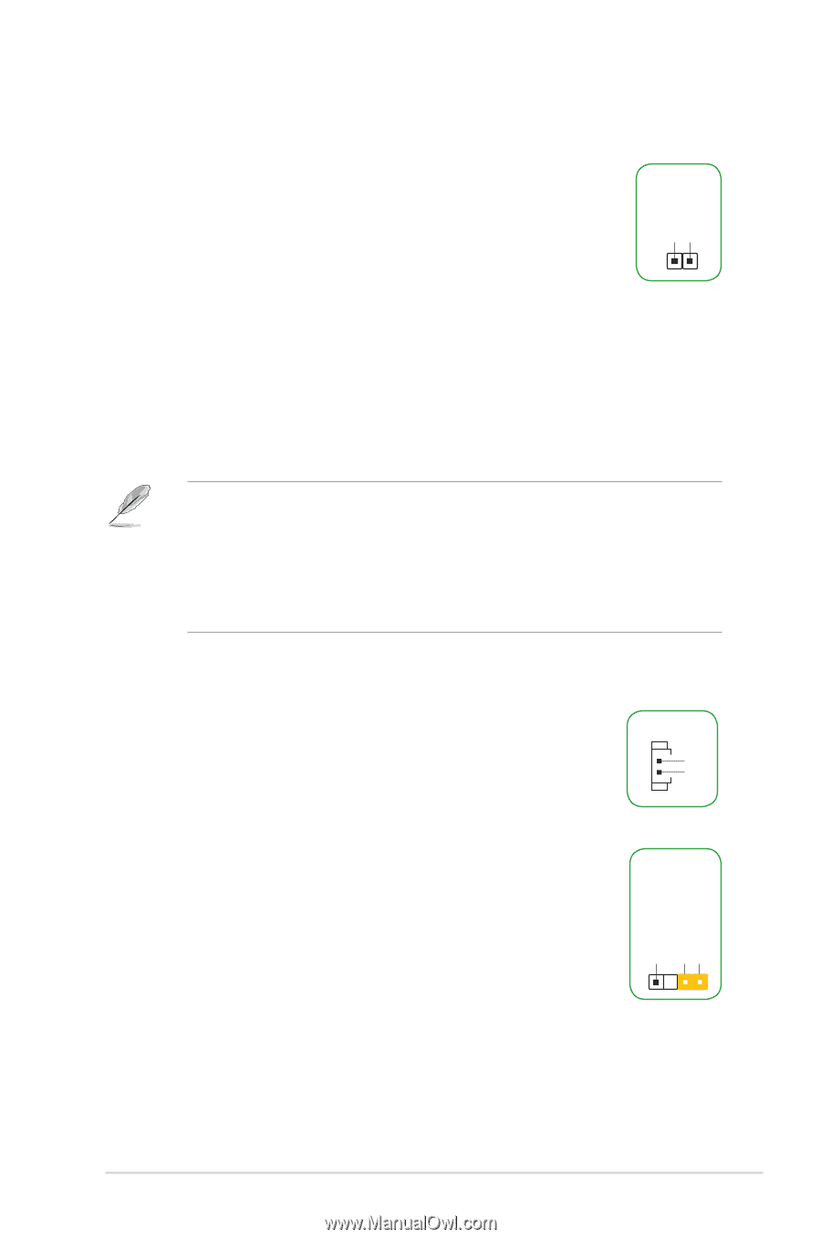
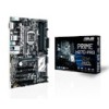
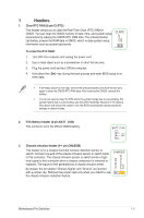
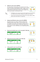
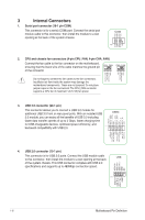
1 Headers 1. Clear RTC RAM (2-pin CLRTC) This header allows you to clear the Real Time Clock (RTC) RAM in CMOS. You can clear the CMOS memory of date, time, and system setup parameters by erasing the CMOS RTC RAM data. The onboard button cell battery powers the RAM data in CMOS, which include system setup information such as system passwords. +3V_BAT GND CLRTC PIN 1 To erase the RTC RAM: 1. Turn OFF the computer and unplug the power cord. 2. Use a metal object such as a screwdriver to short the two pins. 3. Plug the power cord and turn ON the computer. 4. Hold down the key during the boot process and enter BIOS setup to reenter data. • If the steps above do not help, remove the onboard battery and short the two pins again to clear the CMOS RTC RAM data. After clearing the CMOS, reinstall the battery. • You do not need to clear the RTC when the system hangs due to overclocking. For system failure due to overclocking, use the CPU Parameter Recall (C.P.R.) feature. Shut down and reboot the system, then the BIOS automatically resets parameter settings to default values. 2. RTC Battery header (2-pin BATT_CON) This connector is for the lithium CMOS battery. BATT_CON VBAT GND PIN 1 3. Chassis intrusion header (4-1 pin CHASSIS) +5VSB_MB Chassis Signal GND This header is for a chassis-mounted intrusion detection sensor or switch. Connect one end of the chassis intrusion sensor or switch cable to this connector. The chassis intrusion sensor or switch sends a highlevel signal to this connector when a chassis component is removed or replaced. The signal is then generated as a chassis intrusion event. CHASSIS By default, the pin labeled "Chassis Signal" and "Ground" are shorted with a jumper cap. Remove the jumper caps only when you intend to use the chassis intrusion detection feature. Motherboard Pin Definition 1-3
-
 1
1 -
 2
2 -
 3
3 -
 4
4 -
 5
5 -
 6
6 -
 7
7 -
 8
8 -
 9
9 -
10
-
11
-
12
-
13
-
14
-
15
-
16
-
17
-
18
 |
 |