Asus PRIME H310-PLUS R2.0 PRIME H310-PLUS R20 Users Manual English - Page 11
H310 Serial ATA 6.0Gb/s connectors 7-pin SATA6G_1~4, To erase the RTC RAM
 |
View all Asus PRIME H310-PLUS R2.0 manuals
Add to My Manuals
Save this manual to your list of manuals |
Page 11 highlights
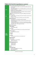
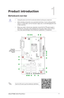
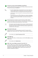
M.2 socket 3 This socket allows you to install an M.2 (NGFF) SSD module. M.2(SOCKET3) • This M.2 socket supports M Key and 2242/2260/2280 storage devices. • When a device in SATA mode is installed on the M.2 socket, SATA_2 port can not be used. Due to the Chipset limitation, when an M.2 device is installed in PCIe mode, the socket is set to PCIe 2.0. Clear RTC RAM (2-pin CLRTC) This header allows you to clear the CMOS RTC RAM data of the system setup information such as date, time, and system passwords. To erase the RTC RAM: 1. Turn OFF the computer and unplug the power cord. 2. Use a metal object such as a screwdriver to short the two pins. 3. Plug the power cord and turn ON the computer. 4. Hold down the key during the boot process and enter BIOS setup to re-enter data. +3V_BAT GND CLRTC PIN 1 If the steps above do not help, remove the onboard battery and short the two pins again to clear the CMOS RTC RAM data. After clearing the CMOS, reinstall the battery. Intel® H310 Serial ATA 6.0Gb/s connectors (7-pin SATA6G_1~4) These connectors connect to Serial ATA 6.0 Gb/s hard disk drives via Serial ATA 6.0 Gb/s signal cables. System panel connector (20-5 pin PANEL) This connector supports several chassis-mounted functions. USB 2.0 connectors (10-1 pin USB78, USB910) Connect a USB module cable to any of these connectors, then install the module to a slot opening at the back of the system chassis. These USB connectors comply with USB 2.0 specifications and support up to 480Mbps connection speed. RGB header This header is for RGB LED strips. The RGB header supports 5050 RGB multi-color LED strips (12V/G/R/B), with a maximum power rating of 3A (12V), and no longer than 3 m. Before you install or remove any component, ensure that the ATX power supply is switched off or the power cord is detached from the power supply. Failure to do so may cause severe damage to the motherboard, peripherals, or components. ASUS PRIME H310-PLUS R2.0 1-3
-
 1
1 -
2
-
3
-
4
-
5
-
 6
6 -
 7
7 -
 8
8 -
 9
9 -
 10
10 -
 11
11 -
 12
12 -
 13
13 -
 14
14 -
 15
15 -
 16
16 -
17
-
18
-
19
-
20
-
21
-
22
-
23
-
24
-
25
-
26
-
27
 |
 |
