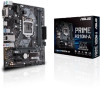
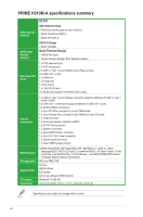
Asus PRIME H310M-A Users Manual English - Page 12
PCI Express 2.0 x1 slots, Front panel audio connector 10-1 pin AAFP - at
 |
View all Asus PRIME H310M-A manuals
Add to My Manuals
Save this manual to your list of manuals |
Page 12 highlights
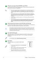
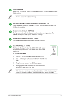
+5V SPDIFOUT GND USB 3.1 Gen 1 (up to 5Gb/s) connector (20-1 pin U31G1_12) Connect a USB 3.1 Gen 1 module to this connector for additional USB 3.1 Gen 1 front or rear panel ports. This connector complies with USB 3.1 Gen 1 specifications and provides faster data transfer speeds of up to 5 Gbps, faster charging time for USB-chargeable devices, optimized power efficiency, and backward compatibility with USB 2.0. USB 2.0 connectors (10-1 pin USB78, USB914) Connect a USB module cable to any of these connectors, then install the module to a slot opening at the back of the system chassis. These USB connectors comply with USB 2.0 specifications and supports up to 480Mbps connection speed. Digital audio connector (4-1 pin SPDIF_OUT) Connect the S/PDIF Out module cable to this connector, then install the module to a slot opening at the back of the system chassis. PIN 1 SPDIF_OUT Serial port connector (10-1 pin COM) Connect the serial port module cable to this connector, then install the module to a slot opening at the back of the system chassis. Front panel audio connector (10-1 pin AAFP) This connector is for a chassis-mounted front panel audio I/O module that supports HD audio standard. Connect one end of the front panel audio I/O module cable to this connector. • We recommend that you connect a high-definition front panel audio module to this connector to avail of the motherboard's high-definition audio capability. • If you want to connect a high-definition front panel audio module to this connector, set the Front Panel Type item in the BIOS setup to [HD Audio]. PCI Express 2.0 x1 slots This motherboard has two PCI Express 2.0 x1 slots that support PCI Express x1 network cards, SCSI cards, and other cards that comply with the PCI Express specifications. PCI Express 3.0/2.0 x16 slot This motherboard supports a PCI Express 3.0/2.0 x16 graphic card that complies with the PCI Express specifications. 1-4 Chapter 1: Product introduction
-
 1
1 -
2
-
3
-
4
-
5
-
6
-
 7
7 -
 8
8 -
 9
9 -
 10
10 -
 11
11 -
 12
12 -
 13
13 -
 14
14 -
 15
15 -
 16
16 -
 17
17 -
18
-
19
-
20
-
21
-
22
-
23
-
24
-
25
-
26
-
27
-
28
-
29
 |
 |
