Asus PRIME H310M-CS R2.0 PRIME H310M-CS R20 Users Manual English - Page 12
Clear RTC RAM 2-pin CLRTC, To erase the RTC RAM
 |
View all Asus PRIME H310M-CS R2.0 manuals
Add to My Manuals
Save this manual to your list of manuals |
Page 12 highlights
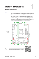
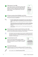
Clear RTC RAM (2-pin CLRTC) This header allows you to clear the CMOS RTC RAM data of the system setup information such as date, time, and system passwords. To erase the RTC RAM: 1. Turn OFF the computer and unplug the power cord. 2. Use a metal object such as a screwdriver to short the two pins. 3. Plug the power cord and turn ON the computer. 4. Hold down the key during the boot process and enter BIOS setup to re-enter data. +3V_BAT GND CLRTC PIN 1 If the steps above do not help, remove the onboard battery and short the two pins again to clear the CMOS RTC RAM data. After clearing the CMOS, reinstall the battery. Chassis intrusion header (4-1 pin CHASSIS) This header is for a chassis-mounted intrusion detection sensor or switch. Connect one end of the chassis intrusion sensor or switch cable to this connector. The chassis intrusion sensor or switch sends a high-level signal to this connector when a chassis component is removed or replaced. The signal is then generated as a chassis intrusion event. Front panel audio connector (10-1 pin AAFP) This connector is for a chassis-mounted front panel audio I/O module that supports HD audio standard. Connect one end of the front panel audio I/O module cable to this connector. • We recommend that you connect a high-definition front panel audio module to this connector to avail of the motherboard's high-definition audio capability. • If you want to connect a high-definition front panel audio module to this connector, set the Front Panel Type item in the BIOS setup to [HD Audio]. PCI Express 2.0 x1 slot This motherboard has one PCI Express 2.0 x1 slot that supports PCI Express x1 network cards, SCSI cards, and other cards that comply with the PCI Express specification. Serial port connector (10-1 pin COM) This connector is for a serial (COM) port. Connect the serial port module cable to this connector, then install the module to a slot opening at the back of the system chassis. PCI Express 3.0/2.0 x16 slot This motherboard supports a PCI Express 3.0/2.0 x16 graphic card that complies with the PCI Express specifications. 1-4 Chapter 1: Product introduction
-
 1
1 -
2
-
3
-
4
-
5
-
6
-
 7
7 -
 8
8 -
 9
9 -
 10
10 -
 11
11 -
 12
12 -
 13
13 -
 14
14 -
 15
15 -
 16
16 -
 17
17 -
18
-
19
-
20
-
21
-
22
-
23
-
24
-
25
 |
 |
