Asus PRIME H610M-A Users Manual English - Page 15
Clear CMOS header, COM Port header, Front Panel Audio header
 |
View all Asus PRIME H610M-A manuals
Add to My Manuals
Save this manual to your list of manuals |
Page 15 highlights
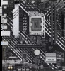
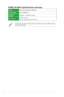
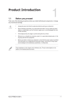
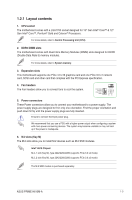
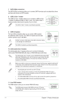
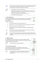
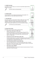
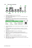
Before you install or remove any component, ensure that the ATX power supply is switched off or the power cord is detached from the power supply. Failure to do so may cause severe damage to the motherboard, peripherals, or components. • Actual lighting and color will vary with LED strip. • If your LED strip does not light up, check if the RGB LED extension cable and the RGB LED strip are connected in the correct orientation, and the 12V connector is aligned with the 12V header on the motherboard. • The LED strip will only light up when the system is powered on. • The LED strip is purchased separately. 12. Clear CMOS header The Clear CMOS header allows you to clear the Real Time Clock (RTC) RAM in the CMOS, which contains the date, time, system passwords, and system setup parameters. To erase the RTC RAM: +3V_BAT GND CLRTC PIN 1 1. Turn OFF the computer and unplug the power cord. 2. Short-circuit pin 1-2 with a metal object or jumper cap for about 5-10 seconds. 3. Plug the power cord and turn ON the computer. 4. Hold down the key during the boot process and enter BIOS setup to re-enter data. DO NOT short-circuit the pins except when clearing the RTC RAM. Short-circuiting or placing a jumper cap will cause system boot failure! If the steps above do not help, remove the onboard button cell battery and short the two pins again to clear the CMOS RTC RAM data. After clearing the CMOS, reinstall the button cell battery. DCD TXD GND RTS RI RXD DTR DSR CTS 13. COM Port header The COM (Serial) Port header allows you to connect a COM port module. Connect the COM port module cable to this header, then install the module to a slot opening on the system chassis. The COM port module is purchased separately. COM PIN 1 AGND NC SENSE1_RETUR SENSE2_RETUR 14. Front Panel Audio header The Front Panel Audio header is for a chassis-mounted front panel audio I/O module that supports HD Audio. Connect one end of the front panel audio I/O module cable to this header. AAFP PORT1 L PORT1 R PORT2 R SENSE_SEND PORT2 L We recommend that you connect a high-definition front panel audio module to this header to avail of the motherboard's high-definition audio capability. HD-audio-compliant pin definition ASUS PRIME H610M-A 1-5
-
 1
1 -
2
-
3
-
4
-
5
-
6
-
7
-
8
-
9
-
 10
10 -
 11
11 -
 12
12 -
 13
13 -
 14
14 -
 15
15 -
 16
16 -
 17
17 -
 18
18 -
 19
19 -
 20
20 -
21
-
22
-
23
-
24
-
25
-
26
-
27
-
28
-
29
-
30
-
31
-
32
-
33
-
34
 |
 |