Asus PRIME J3355I-C User Guide - Page 12
Clear RTC RAM 2-pin CLRTC, To erase the RTC RAM
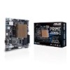 |
View all Asus PRIME J3355I-C manuals
Add to My Manuals
Save this manual to your list of manuals |
Page 12 highlights
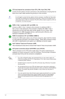
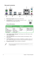
Chassis intrusion connector (4-1 pin CHASSIS) This connector is for a chassis-mounted intrusion detection sensor or switch. Connect one end of the chassis intrusion sensor or switch cable to this connector. The chassis intrusion sensor or switch sends a high-level signal to this connector when a chassis component is removed or replaced. The signal is then generated as a chassis intrusion event. The chassis intrusion detection feature is disabled by default. To enable it, set the Chassis Intrude Detect Support item in the BIOS to [On]. PCI Express 2.0 x4 slot (@x1 mode) This motherboard supports PCI Express 2.0 x4 network cards, SCSI cards, and other cards that comply with the PCI Express specifications. Panel off header (2-pin PANEL_SW) This 2-pin header is for connecting a monitor switch that can turn off the LCD panel display backlight. LPT connector (26-1 pin LPT) The LPT (Line Printing Terminal) connector supports devices such as a printer. LPT standardizes as IEEE 1284, which is the parallel port interface on IBM PCcompatible computers. Clear RTC RAM (2-pin CLRTC) This header allows you to clear the CMOS RTC RAM data of the system setup information such as date, time, and system passwords. To erase the RTC RAM: +3V_BAT GND CLRTC PIN 1 1. Turn OFF the computer and unplug the power cord. 2. Use a metal object such as a screwdriver to short the two pins. 3. Plug the power cord and turn ON the computer. 4. Hold down the key during the boot process and enter BIOS setup to re-enter data. If the steps above do not help, remove the onboard battery and short the two pins again to clear the CMOS RTC RAM data. After clearing the CMOS, reinstall the battery. 1-4 Chapter 1: Product introduction
-
 1
1 -
2
-
3
-
4
-
5
-
6
-
 7
7 -
 8
8 -
 9
9 -
 10
10 -
 11
11 -
 12
12 -
 13
13 -
 14
14 -
 15
15 -
 16
16 -
 17
17 -
18
-
19
-
20
-
21
-
22
-
23
-
24
-
25
-
26
 |
 |
