Asus ROG MAXIMUS IX HERO MAXIMUS IX HERO USER S MANUAL ENGLISH - Page 45
M.2 sockets M.2_1; M.2_2, LED connector 5-pin RGB_LED_STRIP2
 |
View all Asus ROG MAXIMUS IX HERO manuals
Add to My Manuals
Save this manual to your list of manuals |
Page 45 highlights
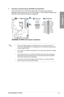
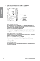
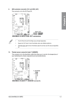
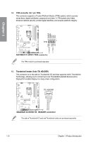
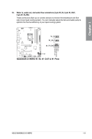
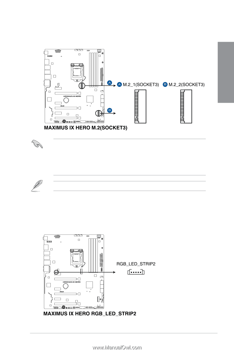
Chapter 1 12. M.2 sockets (M.2_1; M.2_2) These sockets allow you to install M.2 SSD modules. • M.2_1 socket supports PCIe 3.0 x4 and SATA mode M Key design and type 2242 / 2260 / 2280 PCIe storage devices. • M.2_2 socket supports PCIe 3.0 x4 M Key design and type 2242 / 2260 / 2280 / 22110 PCIe storage devices. • These sockets support IRST (Intel® Rapid Storage Technology). The M.2 SSD module is purchased separately. 13. LED connector (5-pin RGB_LED_STRIP2) This LED connector is for connecting LED strips on your cover. ASUS MAXIMUS IX HERO 1-29
-
 1
1 -
2
-
3
-
4
-
5
-
6
-
7
-
8
-
9
-
10
-
11
-
12
-
13
-
14
-
15
-
16
-
17
-
18
-
19
-
20
-
21
-
22
-
23
-
24
-
25
-
26
-
27
-
28
-
29
-
30
-
31
-
32
-
33
-
34
-
35
-
36
-
37
-
38
-
39
-
 40
40 -
 41
41 -
 42
42 -
 43
43 -
 44
44 -
 45
45 -
 46
46 -
 47
47 -
 48
48 -
 49
49 -
 50
50 -
51
-
52
-
53
-
54
-
55
-
56
-
57
-
58
-
59
-
60
-
61
-
62
-
63
-
64
-
65
-
66
-
67
-
68
-
69
-
70
-
71
-
72
-
73
-
74
-
75
-
76
-
77
-
78
-
79
-
80
-
81
-
82
-
83
-
84
-
85
-
86
-
87
-
88
-
89
-
90
-
91
-
92
-
93
-
94
-
95
-
96
-
97
-
98
-
99
-
100
-
101
-
102
-
103
-
104
-
105
-
106
-
107
-
108
-
109
-
110
-
111
-
112
 |
 |
ASUS MAXIMUS IX HERO
1-29
Chapter 1
12.
M.2 sockets (M.2_1; M.2_2)
These sockets allow you to install M.2 SSD modules.
13.
LED connector (5-pin RGB_LED_STRIP2)
This LED connector is for connecting LED strips on your cover.
•
M.2_1 socket supports PCIe 3.0 x4 and SATA mode M Key design and type 2242 /
2260 / 2280 PCIe storage devices.
•
M.2_2 socket supports PCIe 3.0 x4 M Key design and type 2242 / 2260 / 2280 / 22110
PCIe storage devices.
•
These sockets support IRST (Intel
®
Rapid Storage Technology).
The M.2 SSD module is purchased separately.