Asus RS300-E7 RS4 User Guide - Page 15
Front panel features, Rear panel features
 |
View all Asus RS300-E7 RS4 manuals
Add to My Manuals
Save this manual to your list of manuals |
Page 15 highlights
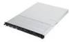
1.4 Front panel features The barebone server displays a simple yet stylish front panel with easily accessible features. The power and reset buttons, LED indicators, and USB port for each Node are located on the front panel. Refer to section 1.7.1 Front panel LEDs for the LED descriptions. Rack screw Hot-swap SATA 6Gb/s HDD bays Hot-swap SATA 3Gb/s HDD bays Rack screw Slim-type optical drive (Optional) USB ports HDD Access LED LAN2/4 LED LAN1/3 LED Message LED Reset button Location LED Location switch Power button Power LED Turn off the system power and detach the power supply before removing or replacing any system component. 1.5 Rear panel features The rear panel includes the expansion slots, system power sockets, and rear fans. The I/O shields with openings for the rear panel connectors on the motherboard are also placed in the real panel. The ports for the USB, VGA, and Gigabit LANs do not appear on the rear panel if the motherboards are not present. Gigabit LAN port 4 Gigabit LAN port 3 Gigabit LAN port 2 Gigabit LAN port 1 VGA port USB ports LAN port 5* PS/2 keyboard port PS/2 mouse port Power cord connector Redundant Power supply * This port is for ASUS ASMB5-iKVM controller card only. ASUS RS300-E7/RS4 1-5
-
 1
1 -
2
-
3
-
4
-
5
-
6
-
7
-
8
-
9
-
 10
10 -
 11
11 -
 12
12 -
 13
13 -
 14
14 -
 15
15 -
 16
16 -
 17
17 -
 18
18 -
 19
19 -
 20
20 -
21
-
22
-
23
-
24
-
25
-
26
-
27
-
28
-
29
-
30
-
31
-
32
-
33
-
34
-
35
-
36
-
37
-
38
-
39
-
40
-
41
-
42
-
43
-
44
-
45
-
46
-
47
-
48
-
49
-
50
-
51
-
52
-
53
-
54
-
55
-
56
-
57
-
58
-
59
-
60
-
61
-
62
-
63
-
64
-
65
-
66
-
67
-
68
-
69
-
70
-
71
-
72
-
73
-
74
-
75
-
76
-
77
-
78
-
79
-
80
-
81
-
82
-
83
-
84
-
85
-
86
-
87
-
88
-
89
-
90
-
91
-
92
-
93
-
94
-
95
-
96
-
97
-
98
-
99
-
100
-
101
-
102
-
103
-
104
-
105
-
106
-
107
-
108
-
109
-
110
-
111
-
112
-
113
-
114
-
115
-
116
-
117
-
118
-
119
-
120
-
121
-
122
-
123
-
124
-
125
-
126
-
127
-
128
-
129
-
130
-
131
-
132
-
133
-
134
-
135
-
136
-
137
-
138
-
139
-
140
-
141
-
142
-
143
-
144
-
145
-
146
-
147
-
148
-
149
-
150
 |
 |
