Asus RS520-E9-RS12-E RS520-E9 Series User Manual - Page 36
Storage devices, Place the tray on a flat and stable surface.
 |
View all Asus RS520-E9-RS12-E manuals
Add to My Manuals
Save this manual to your list of manuals |
Page 36 highlights
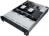
2.4 Storage devices The RS520-E9-RS8 system supports eight (8) 2.5" or 3.5" hot-swap storage devices, the RS520-E9-RS12-E system supports twelve (12) storage devices, and both support two (2) additional hot-swap 2.5" storage devices on the rear panel. The storage device installed in the bay connects to the motherboard SATA/NVMe ports via the SATA/NVMe backplane (SAS drives require an optional ASUS PIKE II card). • On RS520-E9-RS8 models, the onboard controller only supports SATA storage devices by default, if you would like to use SAS storage devices, please install an ASUS PIKE II card (purchased separately). • On RS520-E9-RS12-E models, if you would like to use SATA or SAS storage devices on the backplane, please install an ASUS PIKE II card. To install a 3.5" storage device to the front panel: 1. Push the spring lock to the right (A) then pull the tray lever outward (B) to release the tray. The tray ejects slightly after you pull out the lever. Tray lever Spring lock 2. Firmly hold the tray lever and pull the tray out of the bay. 3. Place the tray on a flat and stable surface. 4. Prepare the 3.5" storage device and the bundled set of screws. 2-8 Chapter 2: Hardware Information
-
 1
1 -
2
-
3
-
4
-
5
-
6
-
7
-
8
-
9
-
10
-
11
-
12
-
13
-
14
-
15
-
16
-
17
-
18
-
19
-
20
-
21
-
22
-
23
-
24
-
25
-
26
-
27
-
28
-
29
-
30
-
 31
31 -
 32
32 -
 33
33 -
 34
34 -
 35
35 -
 36
36 -
 37
37 -
 38
38 -
 39
39 -
 40
40 -
 41
41 -
42
-
43
-
44
-
45
-
46
-
47
-
48
-
49
-
50
-
51
-
52
-
53
-
54
-
55
-
56
-
57
-
58
-
59
-
60
-
61
-
62
-
63
-
64
-
65
-
66
-
67
-
68
-
69
-
70
-
71
-
72
-
73
-
74
-
75
-
76
-
77
-
78
-
79
-
80
-
81
-
82
-
83
-
84
-
85
-
86
-
87
-
88
-
89
-
90
-
91
-
92
-
93
-
94
-
95
-
96
-
97
-
98
-
99
-
100
-
101
-
102
-
103
-
104
-
105
-
106
-
107
-
108
-
109
-
110
-
111
-
112
-
113
-
114
-
115
-
116
-
117
-
118
-
119
-
120
-
121
-
122
-
123
-
124
-
125
-
126
-
127
-
128
-
129
-
130
-
131
-
132
-
133
-
134
-
135
-
136
-
137
-
138
-
139
-
140
-
141
-
142
-
143
-
144
-
145
-
146
-
147
-
148
-
149
-
150
-
151
-
152
-
153
-
154
-
155
-
156
-
157
-
158
-
159
-
160
-
161
-
162
-
163
-
164
-
165
-
166
-
167
-
168
-
169
-
170
-
171
-
172
-
173
-
174
 |
 |
