Asus Rampage Extreme User Manual - Page 98
EPU II Phase Control [Auto], CPU Voltage [Auto], Loadline Calibration [Auto], CPU PLL Voltage [Auto]
 |
UPC - 610839164363
View all Asus Rampage Extreme manuals
Add to My Manuals
Save this manual to your list of manuals |
Page 98 highlights
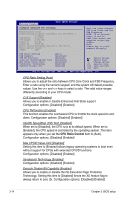
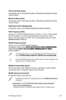
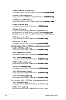
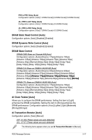
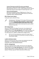
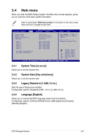
Common Performance Level [05] (This value is auto-detected) Set this item to a higher level for better compatibility or a lower level for better performance. Use the and keys to adjust the value or type the desired value using the numeric keypad. The values range from 1 to 31. Pull-In of CHA PH2 [Disabled] Set this item to [Enabled] to enhance DRAM Channel A, Phase 1 to 2. The number of phases is determined by DRAM frequency and FSB strap. Configuration options: [Disabled] [Enabled] EPU II Phase Control [Auto] Configuration options: [Auto] [Full Phase] The following items-CPU Voltage, CPU PLL Voltage, FSB Termination Voltage, North Bridge Voltage, DRAM Voltage, South Bridge 1.5 Voltage, South Bridge 1.05 Voltage�-��a�r�e��a�d�j�u�s�t�e�d��b�y��ty�p��in��g�t��h��e����d��e���s��i�r��e��d����v��a���l�u��e���s����u��s��i�n���g����th��e��n�u�m��e�r�ic� keypad and press the key. You can also use the and keys to adjust the value. To restore the default setting, type [auto] using the keyboard and press the key. CPU Voltage [Auto] Allows you to select the CPU voltage. The text color in the configuration field corresponds to the onboard CPU LED color, both of which indicate voltage condition. When you set the CPU LED Selection item to [Vcore], the onboard CPU LED displays CPU voltage condition. Refer to page 2-1 for CPU LED definition. The values range from 1.10000V to 2.40000V with a 0.00625V interval. Refer to the CPU documentation before setting the CPU voltage. Setting a high voltage may damage the CPU permanently, and setting a low voltage may make the system unstable. Loadline Calibration [Auto] Allows you to select the CPU Load-Line mode. Set to [Disabled] to follow Intel specifications, or to [Enabled] to improve CPU VDroop directly. Configuration options: [Auto] [Disabled] [Enabled] CPU PLL Voltage [Auto] Allows you to select the CPU PLL voltage. The text color in the configuration field corresponds to the onboard CPU LED color, both of which indicate voltage condition. When you set the CPU LED Selection item to [CPU PLL], the onboard CPU LED displays CPU PLL voltage condition. Refer to page 2-1 for CPU LED definition. The values range from 1.50V to 3.00V with a 0.013V interval. 3-18 Chapter 3: BIOS setup
-
 1
1 -
2
-
3
-
4
-
5
-
6
-
7
-
8
-
9
-
10
-
11
-
12
-
13
-
14
-
15
-
16
-
17
-
18
-
19
-
20
-
21
-
22
-
23
-
24
-
25
-
26
-
27
-
28
-
29
-
30
-
31
-
32
-
33
-
34
-
35
-
36
-
37
-
38
-
39
-
40
-
41
-
42
-
43
-
44
-
45
-
46
-
47
-
48
-
49
-
50
-
51
-
52
-
53
-
54
-
55
-
56
-
57
-
58
-
59
-
60
-
61
-
62
-
63
-
64
-
65
-
66
-
67
-
68
-
69
-
70
-
71
-
72
-
73
-
74
-
75
-
76
-
77
-
78
-
79
-
80
-
81
-
82
-
83
-
84
-
85
-
86
-
87
-
88
-
89
-
90
-
91
-
92
-
 93
93 -
 94
94 -
 95
95 -
 96
96 -
 97
97 -
 98
98 -
 99
99 -
 100
100 -
 101
101 -
 102
102 -
 103
103 -
104
-
105
-
106
-
107
-
108
-
109
-
110
-
111
-
112
-
113
-
114
-
115
-
116
-
117
-
118
-
119
-
120
-
121
-
122
-
123
-
124
-
125
-
126
-
127
-
128
-
129
-
130
-
131
-
132
-
133
-
134
-
135
-
136
-
137
-
138
-
139
-
140
-
141
-
142
-
143
-
144
-
145
-
146
-
147
-
148
-
149
-
150
-
151
-
152
-
153
-
154
-
155
-
156
-
157
-
158
-
159
-
160
-
161
-
162
-
163
-
164
-
165
-
166
-
167
-
168
-
169
-
170
-
171
-
172
-
173
-
174
-
175
-
176
-
177
-
178
-
179
-
180
-
181
-
182
-
183
-
184
-
185
-
186
-
187
-
188
 |
 |