Asus S1-P111 Spresso Hardware User Manual
Asus S1-P111 Manual
 |
View all Asus S1-P111 manuals
Add to My Manuals
Save this manual to your list of manuals |
Asus S1-P111 manual content summary:
- Asus S1-P111 | Spresso Hardware User Manual - Page 1
® S-presso Multimedia System User Guide Hardware Information - Asus S1-P111 | Spresso Hardware User Manual - Page 2
COMPUTER INC. All Rights Reserved. No part of this manual, ASUSTeK COMPUTER INC. ("ASUS"). Product warranty or service will ASUS HAS BEEN ADVISED OF THE POSSIBILITY OF SUCH DAMAGES ARISING FROM ANY DEFECT OR ERROR IN THIS MANUAL OR PRODUCT. SPECIFICATIONS AND INFORMATION CONTAINED IN THIS MANUAL - Asus S1-P111 | Spresso Hardware User Manual - Page 3
2.2 Before you proceed 2-2 2.3 Removing the front panel 2-3 2.4 Removing the cover 2-4 2.5 Removing the power supply unit 2-5 2.6 Installing a CPU 2-6 2.6.1 Removing the CPU fan and heatsink assembly ....... 2-6 2.6.2 CPU installation 2-7 2.6.3 Reinstalling the CPU fan and heatsink assembly - Asus S1-P111 | Spresso Hardware User Manual - Page 4
2.11 2.11 2.12 Reinstalling the power supply unit 2-17 2.11.1 Voltage selector 2-18 2.11.2 Power supply specifications 2-19 Replacing the cover 2-20 Connecting external devices 2-21 Chapter 3: Motherboard info 3.1 Introduction 3-2 3.2 Motherboard layout 3-2 3.3 Jumper 3-3 3.4 Connectors - Asus S1-P111 | Spresso Hardware User Manual - Page 5
5-2 5.3 Support CD information 5-3 5.3.1 Running the support CD 5-3 5.3.2 Drivers menu 5-4 5.3.3 Utilities menu 5-5 5.3.4 ASUS contact information 5-6 5.3.5 Other information 5-6 5.4 Software information 5-8 5.4.1 ASUS Update 5-8 5.4.2 ASUS PC Probe 5-10 5.4.3 Multi-channel audio feature - Asus S1-P111 | Spresso Hardware User Manual - Page 6
for a Class B digital device, pursuant to Part 15 of the FCC Rules. These limits are and used in accordance with manufacturer's instructions, may cause harmful interference to radio determined by turning the equipment off and on, the user is encouraged to try to correct the interference by one - Asus S1-P111 | Spresso Hardware User Manual - Page 7
may become wet. Place the product on a stable surface. • If you encounter technical problems with the product, contact a qualified service technician or your retailer. Unplug the power cord before removing the front panel. Failure to do so can cause you physical injury and damage the system. Lithium - Asus S1-P111 | Spresso Hardware User Manual - Page 8
Safeguards About this guide Audience This guide provides general information and installation instructions about the ASUS S-presso. This guide is intended for experienced users and integrators with hardware knowledge of personal computers. How this guide is organized 1. Chapter 1: System - Asus S1-P111 | Spresso Hardware User Manual - Page 9
Conventions used in this guide W A R N I N G : ASUS hardware and software products. Refer to the ASUS contact information. 2. Optional documentation Your product package may include optional documentation, such as warranty flyers, that may have been added by your dealer. These documents are not part - Asus S1-P111 | Spresso Hardware User Manual - Page 10
CDs • Support CD • ASUS Instant On CD • ASUS Home Theater CD 4 . Documentation • User guide (Hardware Information) • User guide (Software Information) 5 . Remote controller 6 . Power supply unit 7 . ASUS TV/FM card 8 . Optional items • Optical drive • Hard disk drive S-presso Models S1-P111 S1-P112 - Asus S1-P111 | Spresso Hardware User Manual - Page 11
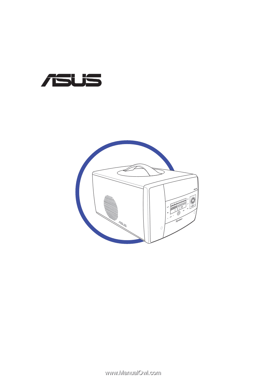
System Introduction Chapter 1 This chapter gives a general description of the ASUS S-presso. The chapter lists the system features including introduction on the front and rear panels, and internal components. ASUS S-presso - Asus S1-P111 | Spresso Hardware User Manual - Page 12
own desktop. The ASUS S-presso is a smart personal computer and a versatile home entertainment system in one. Powered by the ASUS P4P8T motherboard, S-presso delivers robust technology for your computing and multimedia entertainment needs. S-presso supports the Intel® Pentium® 4 processor with up to - Asus S1-P111 | Spresso Hardware User Manual - Page 13
d o o r . Inside this door are the front panel input/ output ports. 7 . S y s t e m p o w e r b u t t o n . Press this button to exit Instant On. The system then powers on and enters the S-presso operating system. 8 . P L A Y / P A U S E s e n s o r . Plays the audio CD/DVD or DVD/VCD in the optical - Asus S1-P111 | Spresso Hardware User Manual - Page 14
t a n t O n P O W E R s e n s o r . Touch this sensor to turn on the S-presso Instant On feature. The Instant On feature allows you to play DVD/VCD movie, CD audio tracks, or MP3 files without entering the S-presso operating system. 1 1 . M O D E S W I T C H s e n s o r . Touch this sensor to switch - Asus S1-P111 | Spresso Hardware User Manual - Page 15
several I/O ports are located inside the internal front panel doors. Press the access buttons to open the internal front panel doors. S1-P111 17 18 19 20 21 22 23 24 25 26 Front panel (open) 1 7 . S e c u r e D i g i t d r i v e . This is an optional DVD-ROM/CD-RW/DVD-RW drive. ASUS S-presso 1-5 - Asus S1-P111 | Spresso Hardware User Manual - Page 16
panel The S-presso rear panel includes the power socket and several I/O ports that allow convenient connection of devices. 6 1 7 8 2 3 9 4 10 5 11 12 13 14 15 16 17 18 1 . P o w e r s u p p l y u n i t f a n . This fan provides ventilation inside the power supply becomes Front Speaker Out - Asus S1-P111 | Spresso Hardware User Manual - Page 17
Audio ports function variation Port Light Blue Lime Pink Headphone/2-Channel Line In Line Out Mic In 4-Channel No function Front Speaker Out Surround 6-Channel LFE Output*/Center Front an AGP card. 1 8 . P C I s l o t c o v e r . Remove this cover to install a PCI card. ASUS S-presso 1-7 - Asus S1-P111 | Spresso Hardware User Manual - Page 18
of the system when you remove the top cover. The installed components are labeled for your reference. Proceed to Chapter 2 for instructions on installing other system components. 1 2 3 4 5 6 7 8 1. Optical drive bay 2. HDD drive bay 3. Storage card slot 4. I/O slot 5. DIMM sockets 6. Fan and - Asus S1-P111 | Spresso Hardware User Manual - Page 19
panel The S-presso LED panel on the S-presso S1-P111 model displays different system information depending on the system mode. Below are the LED panel MP3 files without entering the S-presso operating system. For details, refer to the S o f t w a r e I n f o r m a t i o n user guide. • Launch the H o - Asus S1-P111 | Spresso Hardware User Manual - Page 20
is powered off, in soft-off or stand-by mode, S3 (Suspend-to-RAM), or S4 (Suspend-to-Disk) state, this displays the system time. The panel displays the system time in 24-hour format. Enter the BIOS setup or the S-presso operating system to adjust the time. In Instant On, this displays the current - Asus S1-P111 | Spresso Hardware User Manual - Page 21
Basic installation Chapter 2 This chapter provides step-by-step instructions on how to install components in the system. ASUS S-presso - Asus S1-P111 | Spresso Hardware User Manual - Page 22
power supply case, before handling components to avoid damaging them due to static electricity. • Hold components by the edges to avoid touching the ICs on them. • Whenever you uninstall any component, place it on a grounded antistatic pad or in the bag that came with the component. The motherboard - Asus S1-P111 | Spresso Hardware User Manual - Page 23
you physical injury and damage the system. To remove the front panel: 1. Locate the groove under the front panel. 2. Position your four fingers under the groove, with your thumb supporting the lower portion of the front panel. 3. Slightly pull towards you until the lower portion disengages from - Asus S1-P111 | Spresso Hardware User Manual - Page 24
2.4 Removing the cover To remove the cover: 1. On the rear panel, locate the thumbscrew that secures the cover to the chassis. 2. Turn the thumbscrew counterclockwise unti it gets loose. The thumbscrew cannot be removed from the - Asus S1-P111 | Spresso Hardware User Manual - Page 25
power supply unit You must remove the power supply unit (PSU) before you can install a central processing unit (CPU) and other system components. To remove the PSU: 1. Disconnect the power plugs on the motherboard. 2. Locate the lever that secures the PSU. 3. Push down the lever to release the PSU - Asus S1-P111 | Spresso Hardware User Manual - Page 26
2.6 Installing a CPU The motherboard comes with a surface mount 478-pin Zero Insertion Force (ZIF) socket. This socket is designed for an Intel® Pentium® 4 processor with up to 3.4 GHz core frequency and 800 MHz FSB. 2.6.1 Removing the CPU fan and heatsink assembly The system package includes a pre- - Asus S1-P111 | Spresso Hardware User Manual - Page 27
the socket such that its marked corner (gold mark) matches the base of the socket lever. 5. Carefully insert the CPU into the socket until it fits in place. 6. Push down the socket lever to secure the CPU. The lever clicks on the side tab to indicate that it is locked. 4 5 3 2 1 ASUS S-presso 2-7 - Asus S1-P111 | Spresso Hardware User Manual - Page 28
fan and heatsink assembly To re-install the CPU fan and heatsink assembly: 1. Position the CPU fan and heatsink assembly on top of the installed CPU. 2. Using a Phillips screw driver, secure the CPU fan and heatsink assembly to the motherboard with the four screws your removed earlier. 3. Connect - Asus S1-P111 | Spresso Hardware User Manual - Page 29
that you obtain memory modules from the same vendor. • This motherboard only supports x4, x8, x16 chips per module DDR DIMMs. • Make sure that the memory frequency matches the CPU FSB (Front Side Bus). Refer to the Memory frequency/CPU FSB synchronization table on the next page. ASUS S-presso 2-9 - Asus S1-P111 | Spresso Hardware User Manual - Page 30
Memory frequency/CPU FSB synchronization The system motherboard supports different memory frequencies depending on the CPU FSB (Front Side Bus) and the type of DDR DIMM. CPU FSB 800 MHz 533 MHz 400 MHz DDR DIMM Type PC3200/PC2700*/PC2100 PC2700/PC2100 PC2100 Memory Frequency 400/333*/266 MHz 333/ - Asus S1-P111 | Spresso Hardware User Manual - Page 31
or +1.5V AGP cards. The P4P8T motherboard does not support 3.3V AGP cards. Unplug the power cord before adding or removing expansion cards. Failure to do so can cause you physical injury and damage the motherboard. P4P8T ® P4P8T Accelerated Graphics Port (AGP) Keyed for 1.5v ASUS S-presso 2-11 - Asus S1-P111 | Spresso Hardware User Manual - Page 32
towards the direction of the arrow. 2 3 4. Align the card connector with the slot and press firmly until the card is completely seated in the slot. 5. Replace the hinge lock to secure the card to the chassis. 6. Press down firmly until the hinge lock snaps in place. 6 5 2-12 Chapter 2: Basic - Asus S1-P111 | Spresso Hardware User Manual - Page 33
13 Numeric Data Processor 14* Primary IDE IRQ assignments for this motherboard A B CDE PCI drivers support "Share IRQ" or that the cards do not need IRQ assignments; otherwise, conflicts will arise between the two PCI groups, making the system unstable and the card inoperable. ASUS S-presso - Asus S1-P111 | Spresso Hardware User Manual - Page 34
and power plug. Refer to the optical drive documentation on how to set the optical drive jumper to Master. To install an optical drive: 1. Drive a screw on each side of the optical drive as shown. 2. Remove the front panel. Refer to section "2.3 Removing the front panel" for instructions. 3. Slide - Asus S1-P111 | Spresso Hardware User Manual - Page 35
power cable from the power supply unit to the power motherboard. See page 3-8 for the location of the secondary IDE connector. 9. Connect the other end of the audio cable to the 4-pin CD1 connector on the motherboard. See page 3-8 for the location of the CD audio connector. 5 6 7 ASUS S-presso - Asus S1-P111 | Spresso Hardware User Manual - Page 36
the IDE connector on the drive. 6. Connect a 4-pin power plug from 5 the power supply unit to the HDD power connector. 7. Connect the other end of the IDE ribbon cable to the primary 6 IDE connector (blue connector labeled PRI_IDE) on the motherboard. See page 3-8 for the location of the - Asus S1-P111 | Spresso Hardware User Manual - Page 37
their respective grooves. 2. Slide the PSU toward the direction of the rear panel until it fits in place. 3. Connect the power plugs to the connectors on the motherboard. See next page for details. Make sure that the PSU cables do not interfere with the CPU and/or chassis fans. ASUS S-presso 2-17 - Asus S1-P111 | Spresso Hardware User Manual - Page 38
location of these connectors. 2.11.1 Voltage selector The PSU has a 115 V/230 V voltage selector switch located beside the power connector. Use this switch to select the appropriate voltage according to the voltage supply in your area. If the voltage supply in your area is 100-127 V, set the switch - Asus S1-P111 | Spresso Hardware User Manual - Page 39
2.11.2 Power supply specifications Input characteristics Input Voltage Range Range 1 Range 2 Input Frequency that is always present when AC main voltage is present. • The maximum continuous average DC output power should not exceed 220 W. • The maximum combined load on +5 V and +3.3 V outputs - Asus S1-P111 | Spresso Hardware User Manual - Page 40
Output ripple Parameter +3.3 V +5 V +12 V -12 V +5 VSB Ripple & Noise Max 100 100 150 150 100 Unit mVp-p mVp-p mVp-p mVp-p mVp-p 2.11 Replacing the cover To replace the cover: 1. Push down the top cover. 2.. Push to the direction of the arrow until the rear portion of the cover aligns with the - Asus S1-P111 | Spresso Hardware User Manual - Page 41
3. Tighten the screw by turning it clockwise to secure the cover to the rear panel. 2.12 Connecting external devices To the front panel S1-P111 Headphone Mic ASUS S-presso Scanner 2-21 - Asus S1-P111 | Spresso Hardware User Manual - Page 42
To the rear panel PS/2 mouse Printer Power outlet RJ-45 PS/2 KB VGA monitor Line Out Line In Mic USB USB mouse printer Audio devices 2-22 Chapter 2: Basic installation - Asus S1-P111 | Spresso Hardware User Manual - Page 43
Motherboard info Chapter 3 This chapter gives information about the motherboard that comes with the system. This chapter includes the motherboard layout, jumper settings, and connector locations. ASUS S-presso - Asus S1-P111 | Spresso Hardware User Manual - Page 44
3.1 Introduction The ASUS P4P8T motherboard comes already installed in the ASUS S-presso barebone system. This chapter provides technical information about the motherboard for future upgrades or system reconfiguration. 3.2 Motherboard layout 24.89cm (9.8in) ATX Power Connector Super I/O PS/2 T: - Asus S1-P111 | Spresso Hardware User Manual - Page 45
passwords. To erase the RTC RAM: 1. Turn OFF the computer and unplug the power cord. 2. Remove the battery. 3. Move the jumper cap P4P8T ® P4P8T Clear RTC RAM CLRTC 12 23 Normal (Default) Clear CMOS The system automatically turns on when you clear the CMOS after first reboot. ASUS S-presso - Asus S1-P111 | Spresso Hardware User Manual - Page 46
with USB 2.0 specification that supports up to 480 Mbps connection speed. USB Power USBP2- USBP2+ GND NC P4P8T ® P4P8T USB connector 1 5 USB56 6 10 USB Power USBP3- USBP3+ GND USB78 1 P4P8T ® P4P8T USB connector USB Power USBP2- USBP2+ GND +5V Power Botton USB Power USBP3- USBP3 - Asus S1-P111 | Spresso Hardware User Manual - Page 47
a chassis-mounted front panel audio I/O module that supports AC`97 audio standard. Connect one end of the front panel audio I/O module cable to this connector. Line out_L NC Line out_R MICPWR MIC2 P4P8T ® FP_AUDIO P4P8T Front panel audio connector ASUS S-presso BLINE_OUT_L BLINE_OUT_R +5VA - Asus S1-P111 | Spresso Hardware User Manual - Page 48
connectors support cooling fans of 350 m A ~ 2000 mA (24 W max.) or a total of 1 A ~ 3.48 A (41.76 W max) at +12 V. Connect the fan cables to the fan connectors on the motherboard, making sure that the black wire of each cable matches the ground pin of the connector. P4P8T ® P4P8T Fan connectors - Asus S1-P111 | Spresso Hardware User Manual - Page 49
ATXPWR +12.0Volts +5V Standby Power Good Ground +5.0 Volts Ground +5.0 Volts Ground +3.3 Volts +3.3 Volts P4P8T ® P4P8T ATX power connector ATX12V +12V DC Ground +5.0 Volts +5.0 Volts -5.0 Volts Ground Ground Ground Power Supply On Ground -12.0Volts +3.3Volts +12V DC Ground ASUS S-presso 3-7 - Asus S1-P111 | Spresso Hardware User Manual - Page 50
allow you to receive stereo audio input from sound sources such as a CD-ROM, TV tuner, or MPEG card. AUX1 (White) CD1 (Black) Right Audio Channel Ground Left Audio Channel Right Audio Channel Ground Left Audio Channel P4P8T ® P4P8T Internal audio connectors 3-8 Chapter 3: Motherboard info - Asus S1-P111 | Spresso Hardware User Manual - Page 51
P4P8T ® P4P8T SATA connectors Parallel ATA and Serial ATA device configurations Following are the Parallel ATA and Serial ATA device configurations supported by Intel ICH5 specifications C - - S-ATA Port 0 Port 1 (1 device) (1 device) - - Legend: Supported - Disabled ASUS S-presso 3-9 - Asus S1-P111 | Spresso Hardware User Manual - Page 52
panel on the front panel of the S1-P111 model. P4P8T ® P4P8T LCD_PANEL connector LCD_PANEL +5VSB PIC_STB# PIC_CLK PIC_CLK PIC_STB# DJ_PLAY DJ_SCANFW SMBDATA SMBCLK DJ_VOLUP DJ_STOP# GND PIC_DOUT PIC_DIN PIC_DIN PIC_DOUT +5V DJ_SCANRW +5VSB GND +12V DJ_VOLDN 3-10 Chapter 3: Motherboard info - Asus S1-P111 | Spresso Hardware User Manual - Page 53
10. System panel connector (8-1 pin PANEL) This connector accommodates several system front panel functions. IDE_LED Power LED IDE_LEDIDE_LED+ PLEDPLED+ PANEL Ground PWR P4P8T ® P4P8T System panel connector ATX Power Switch* * Requires an ATX power supply. • System power LED (2-pin PLED) - Asus S1-P111 | Spresso Hardware User Manual - Page 54
3-12 Chapter 3: Motherboard info - Asus S1-P111 | Spresso Hardware User Manual - Page 55
Chapter 4 This chapter tells how to change system settings through the BIOS Setup menus and describes the BIOS parameters. BIOS information ASUS S-presso 1 - Asus S1-P111 | Spresso Hardware User Manual - Page 56
b l e f l o p p y d i s k in case you need to restore the BIOS in the future. Copy the original motherboard BIOS using the AFUDOS or the ASUS Update utilities. • A w o r k i n g B I O S f i l e for this motherboard is in the support CD. Use this file only when you do not have a copy of the original - Asus S1-P111 | Spresso Hardware User Manual - Page 57
2. Copy the original (or the latest) motherboard BIOS to the bootable floppy disk. 4.1.2 Using AFUDOS to copy the current BIOS The AFUDOS.EXE utility can also be used to copy the current system BIOS settings to a floppy or hard disk. The copy can be used as a backup in case - Asus S1-P111 | Spresso Hardware User Manual - Page 58
asus.com) to download the latest BIOS file for your motherboard. Save the BIOS file to a bootable floppy disk. Write down the BIOS file name to a piece of paper. You need to type the e x a c t B I O S f i l e n a m e at the prompt. 2. Copy the AFUDOS.EXE utility from the support screen displays the - Asus S1-P111 | Spresso Hardware User Manual - Page 59
afudos /ip4p8t.rom AMI Firmware Update Utility - Version 1.10 Copyright (C) 2002 American Megatrends, Inc. All rights reserved. Reading file ..... done Erasing flash .... done Writing flash .... 0x0008CC00 (9%) Verifying flash .. done A:\> 5. Reboot the system from the hard disk. ASUS S-presso 4-5 - Asus S1-P111 | Spresso Hardware User Manual - Page 60
floppy disk and using a DOS-based utility. The EZ Flash is built-in the BIOS LPC chip so it is accessible by simply pressing + during the Power-On Self Tests (POST). To update the BIOS using ASUS EZ Flash: 1. Visit the ASUS website (www.asus.com) to download the latest BIOS file for your - Asus S1-P111 | Spresso Hardware User Manual - Page 61
restore BIOS from the motherboard support CD, or from a floppy disk that contains the BIOS file, in case the current BIOS on the motherboard fails or gets corrupted. • Prepare the s u p p o r t C D that came with the motherboard or a floppy disk that contains the motherboard BIOS (P4P8T.ROM) before - Asus S1-P111 | Spresso Hardware User Manual - Page 62
CD in the optical drive. The support CD contains the original BIOS for this motherboard. Bad BIOS checksum. Starting BIOS recovery... Checking for floppy... Floppy not found! Checking for CD-ROM... CD-ROM found. Reading file "p4p8t.rom". Completed. Start flashing... DO NOT shut down or reset the - Asus S1-P111 | Spresso Hardware User Manual - Page 63
BIOS in Windows® environment. This utility is available in the support CD that comes with the motherboard package. ASUS Update requires an Internet connection either through a network or an Internet Service Provider (ISP). To install ASUS Update: 1. Place the support CD in the optical drive. The - Asus S1-P111 | Spresso Hardware User Manual - Page 64
you selected updating/ downloading from the Internet, select the ASUS FTP site nearest you to avoid network traffic, or choose A u t o S e l e c t. Click N e x t. 4. From the FTP site, select the BIOS version that you wish to download. Click N e x t. 5. Follow the screen instructions to complete the - Asus S1-P111 | Spresso Hardware User Manual - Page 65
stores the Setup utility. When you start up the computer, the system provides you with the opportunity to run this program. Press during the Power-On Self Test (POST) to enter the Setup utility, otherwise, POST , and may not exactly match what you see on your screen. ASUS S-presso 4-11 - Asus S1-P111 | Spresso Hardware User Manual - Page 66
System Information [11:10:19] [Tue, 06/29/2004] [English] [Maxtor 6Y080L0] [ASUS CDS520/] [Not Detected] [Not Detected] [Not Detected] [Not Detected] Use [ENTER], [ For changing the advanced system settings Power For changing the advanced power management (APM) configuration Boot For - Asus S1-P111 | Spresso Hardware User Manual - Page 67
displays the specific items for that menu. For example, selecting M a i n shows the Main menu items. The other items (Advanced, Power ASUS user-configurable, you may change the value of the field opposite the item. You can not select an item that is not user display e y s to display the other items on - Asus S1-P111 | Spresso Hardware User Manual - Page 68
IDE Slave Third IDE Master Fourth IDE Master IDE Configuration System Information [11:10:19] [Tue, 06/29/2004] [English] [Maxtor 6Y080L0] [ASUS CDS520/] [Not Detected] [Not Detected] [Not Detected] [Not Detected] Use [ENTER], [TAB] or [SHIFT-TAB] to select a field. Use [+] or [-] to configure - Asus S1-P111 | Spresso Hardware User Manual - Page 69
display the IDE device information. Primary IDE Master Device : Hard Disk Vendor : Maxtor 6Y080L0 Size : 81.9GB LBA Mode : Supported SMART Monitoring: Supported Type LBA and are not user-configurable. These specifically configuring a CD-ROM drive. Select ARMD (ATAPI Removable Media supports - Asus S1-P111 | Spresso Hardware User Manual - Page 70
IDE devices installed in the system. Select an item then press to configure the item. IDE Configuration Onboard IDE Operate Mode Enhanced Mode Support On IDE Detect Time Out (Sec) [Enhanced Mode] [S-ATA] [35] Set [Compatible Mode] when Legacy OS (i.e. WIN ME, 98, NT4.0, MS DOS) is used - Asus S1-P111 | Spresso Hardware User Manual - Page 71
: Intel(R) Celeron(R) CPU 1.70GHz : 1700MHz :1 System Memory Size : 120MB AMI BIOS This item displays the auto-detected BIOS information. Processor This item displays the auto-detected CPU specification. System Memory This item displays the auto-detected system memory. ASUS S-presso 4-17 - Asus S1-P111 | Spresso Hardware User Manual - Page 72
Configuration Chipset Onboard Devices Configuration PCI PnP USB Configuration Configure CPU. 4.4.1 CPU Configuration The items in this menu show the CPU-related information auto-detected by BIOS. Configure advanced CPU settings Manufacturer Brand String Frequency FSB Speed : Intel(R) : Intel - Asus S1-P111 | Spresso Hardware User Manual - Page 73
advanced chipset settings. Select an item then press to display the sub-menu. Advanced Chipset settings [AGP/Int-VGA] [Enabled, 8MB] [ 64MB] Boot Display Device Flat Panel type TV Standard MPS Revision [Auto] [640x480LVDS] [Auto] : [4 Clocks] [3 Clocks] [2 Clocks] ASUS S-presso 4-19 - Asus S1-P111 | Spresso Hardware User Manual - Page 74
] [CRT] [TV] [EFP] [LFP] [CRT+EFP] [CRT+LFP] Flat Panel Display [640x480LVDS] Allows you to select the flat panel display resolution when you selected LCD Flat Panel [LFP] as your boot display device. Configuration options: [640x480LVDS] [800x600LVDS] [1024x768LVDS] [1280x1024LVDS] [1400x1050LVDS - Asus S1-P111 | Spresso Hardware User Manual - Page 75
you to select the TV standard when you selected TV as your boot display device. Configuration options: [Auto] [NTSC_M] [NTSC_M_J] [NTSC_433] [NTSC_N [1.4] [1.1] 4.4.3 Onboard Devices Configuration OnBoard AC'97 Audio OnBoard LAN OnBoard LAN Boot ROM Parallel Port Address Parallel ASUS S-presso 4-21 - Asus S1-P111 | Spresso Hardware User Manual - Page 76
Parallel Port Address [378] Allows you to select the Parallel Port base addresses. Configuration options: [Disabled] [378] [278] Parallel Port Mode [EPP+ECP] Allows you to select the Parallel Port mode. Configuration options: [Normal] [EPP] [ECP] [EPP+ECP] EPP Version [1.9] Allows selection of the - Asus S1-P111 | Spresso Hardware User Manual - Page 77
ISA graphics device is installed in the system so that the latter can function correctly. Setting to [Disabled] deactivates this feature. Configuration options: [Disabled] [Enabled] ASUS S-presso 4-23 - Asus S1-P111 | Spresso Hardware User Manual - Page 78
[Disabled] [Enabled] IRQxx [Available] When set to [Available], the specific IRQ is free for use of PCI/PnP devices. When set to [Reserved Enter> to display the configuration options. USB Configuration Module Version : 2.22.4-5.3 USB Devices Enabled : None USB Function Legacy USB Support USB 2.0 - Asus S1-P111 | Spresso Hardware User Manual - Page 79
HDD formatted drive to boot as FDD (for example, ZIP drive). The Device and Emulation Type items appear only when USB storage devices are installed. ASUS S-presso 4-25 - Asus S1-P111 | Spresso Hardware User Manual - Page 80
. Configuration options: [S1 (POS) Only] [S3 Only] [Auto] 4.5.2 Repost Video on S3 Resume [No] Determines whether to invoke VGA BIOS POST on S3/STR resume. Configuration options: [No] [Yes] 4.5.3 ACPI 2.0 Support [No] Allows you to add more tables for ACPI 2.0 specifications. Configuration options - Asus S1-P111 | Spresso Hardware User Manual - Page 81
On, the system goes on after an AC power loss. Configuration options: [Power Off] [Power On] Power On By PS/2 Devices [Disabled] Allows you to use specific keys on the keyboard or the mouse to turn on the system. This feature requires an ATX power supply that provides at least 1A on the +5VSB lead - Asus S1-P111 | Spresso Hardware User Manual - Page 82
CPU Temperature CPU Fan Speed Chassis Fan Speed VCORE Voltage 3.3V Voltage 5V Voltage 12V Voltage SMART Q-Fan Function [36° C/96.5° F] [44° C/111 displays the CPU, chassis, and power fan speeds in rotations per minute (RPM). If any of the fans is not connected to the motherboard, the specific ASUS - Asus S1-P111 | Spresso Hardware User Manual - Page 83
you to change the system boot options. Select an item then press to display the sub-menu. Boot Settings Boot Device Priority Removable Drives Boot Settings Configuration Security Specifies installed in the system. Configuration options: [xxxxx Drive] [Disabled] ASUS S-presso 4-29 - Asus S1-P111 | Spresso Hardware User Manual - Page 84
On ROM Display Mode Bootup Num-Lock PS/2 Mouse Support Typematic Rate Boot to OS/2 Wait for 'F1' If Error Hit 'DEL' Message Display Interrupt 19 display feature. Configuration options: [Disabled] [Enabled] Make sure that the Full Screen Logo item is set to [Enabled] if you want to use the ASUS - Asus S1-P111 | Spresso Hardware User Manual - Page 85
, the system displays the message "Press DEL to run Setup" during POST. Configuration options: [Disabled] [Enabled] Interrupt 19 Capture [Disabled] When set to [Enabled], this function allows the option ROMs to trap Interrupt 19. Configuration options: [Disabled] [Enabled] ASUS S-presso 4-31 - Asus S1-P111 | Spresso Hardware User Manual - Page 86
Select an item then press to display the configuration options. Security Settings Supervisor Password User Password Change Supervisor Password Boot Sector Virus Protection (RTC) RAM. Refer to section "3.3 Jumper" for instructions on erasing the RTC RAM. 4-32 Chapter 4: BIOS information - Asus S1-P111 | Spresso Hardware User Manual - Page 87
all the fields in the Setup utility. Change User Password Select this item to set or change the user password. The User Password item on top of the User Password item now shows I n s t a l l e d. To change the user password, follow the same steps as in setting a user password. ASUS S-presso - Asus S1-P111 | Spresso Hardware User Manual - Page 88
user password. Password Check [Setup] When set to [Setup], BIOS checks for user password when accessing the Setup utility. When set to [Always], BIOS checks for user by an onboard backup battery and stays on even when the PC is turned off. When you select this option, a confirmation window appears. - Asus S1-P111 | Spresso Hardware User Manual - Page 89
window appears. Select [Yes] to load default values. Select Exit Saving Changes or make other changes before saving the values to the non-volatile RAM. ASUS S-presso 4-35 - Asus S1-P111 | Spresso Hardware User Manual - Page 90
4-36 Chapter 4: BIOS information - Asus S1-P111 | Spresso Hardware User Manual - Page 91
Starting up Chapter 5 This chapter helps you power up the system and install drivers and utilities from the support CD. ASUS S-presso - Asus S1-P111 | Spresso Hardware User Manual - Page 92
For model S1-P111 with Instant On feature, make sure you have installed Instant On b e f o r e proceeding to this section. Refer to Chapter 1 of the S o f t wa r e I n f o r m a t i o n guide for instructions on installing Instant On. 5.1 Installing an operating system The S-presso system supports - Asus S1-P111 | Spresso Hardware User Manual - Page 93
S-presso system contains useful software and several utility drivers that enhance the motherboard features. • Screen display and driver options may not be the same for other operating system versions. • The contents of the support CD are subject to change at any time without notice. Visit the ASUS - Asus S1-P111 | Spresso Hardware User Manual - Page 94
item installs the Intel® Chipset INF Update Program. This driver enables Plug-n-Play INF support for the Intel® chipset components on the motherboard. When installed to the target system, this driver provides the method for configuring the chipset components. You can install this utility using three - Asus S1-P111 | Spresso Hardware User Manual - Page 95
other software that the motherboard supports. ASUS PC Probe This utility continuously monitors vital system information such as fan rotations, CPU temperature, and system voltages, and alerts you on any detected problems. This utility helps you keep your computer in a healthy operating condition - Asus S1-P111 | Spresso Hardware User Manual - Page 96
to display the ASUS contact information. 5.3.5 Other information The icons on the top right side of the screen give additional information on the motherboard and the contents of the support CD. Click an icon to display the specified information. Motherboard info Displays the general specifications - Asus S1-P111 | Spresso Hardware User Manual - Page 97
Displays the support CD contents in graphical format. Technical support form Displays the ASUS Technical Support Request Form that you have to fill out when requesting technical support. Filelist Displays the contents of the support CD and a brief description of each in text format. ASUS S-presso - Asus S1-P111 | Spresso Hardware User Manual - Page 98
in the support CD have wizards that will conveniently guide you through the installation. View the online help or readme file that came with the software for more information. 5.4.1 ASUS Update The ASUS Update is a utility that allows you to update the motherboard BIOS. This utility requires an - Asus S1-P111 | Spresso Hardware User Manual - Page 99
The BIOS ROM information is displayed. Click Flash to update the BIOS. If you selected the option to update the BIOS from a file, a window pops up prompting you to locate the file. Select the file, click Save, then follow the screen instructions to complete the update process. ASUS S-presso 5-9 - Asus S1-P111 | Spresso Hardware User Manual - Page 100
, voltages, and temperatures. This utility also allows you to check other information about your computer, including hard disk space, memory usage, and CPU type, CPU speed, and internal/external frequencies through the DMI Explorer. Starting ASUS PC Probe When ASUS PC Probe starts, a splash screen - Asus S1-P111 | Spresso Hardware User Manual - Page 101
Using ASUS PC Probe Monitoring tab Monitor Summary Shows a summary of the items being monitored. Temperature Monitor Shows the system temperature (for supported processors only). Temperature Warning threshold decrease the threshold level) Voltage Monitor Shows the system voltages. ASUS S-presso 5-11 - Asus S1-P111 | Spresso Hardware User Manual - Page 102
Settings Lets you set threshold levels and polling intervals or refresh times of the system temperature, fan rotation, and voltages. History Lets you record the monitoring activity of a certain component of the system for future reference. Information tab Hard Drive Shows the used and free space of - Asus S1-P111 | Spresso Hardware User Manual - Page 103
the system, such as CPU type, CPU speed, and internal/external frequencies, and memory size. Utility tab Utility Lets you run programs outside of the ASUS Probe modules. To run a program, click E x e c u t e P r o g r a m. N O T E : This feature is currently unavailable. ASUS PC Probe Task Bar Icon - Asus S1-P111 | Spresso Hardware User Manual - Page 104
o n from the support CD that came with the motherboard package to activate the 6-channel audio feature. You must use 4-channel or 6-channel speakers for this setup. Setting to multi-channel audio After installing the audio driver, follow these instructions to adjust the audio settings and avail the - Asus S1-P111 | Spresso Hardware User Manual - Page 105
button. While testing, you will see a black circle moving on the screen indicating the audio path. The P l a y T e s t N o i s e button down menu to display a list of options. Choose the desired setting. 12. Click A p p l y, then click O K when finished. 13. Reboot the computer. ASUS S-presso 5-15 - Asus S1-P111 | Spresso Hardware User Manual - Page 106
Adjusting the microphone settings 1. Click on the Microphone A d v a n c e d button to display the A d v a n c e d Controls for Microphone window. 2. Check the box opposite M i c 2 S e l e c t to enable the front panel microphone. 3. Click C l o s e for the new settings to take effect. 5-16 The
-
 1
1 -
 2
2 -
 3
3 -
 4
4 -
 5
5 -
 6
6 -
 7
7 -
8
-
9
-
10
-
11
-
12
-
13
-
14
-
15
-
16
-
17
-
18
-
19
-
20
-
21
-
22
-
23
-
24
-
25
-
26
-
27
-
28
-
29
-
30
-
31
-
32
-
33
-
34
-
35
-
36
-
37
-
38
-
39
-
40
-
41
-
42
-
43
-
44
-
45
-
46
-
47
-
48
-
49
-
50
-
51
-
52
-
53
-
54
-
55
-
56
-
57
-
58
-
59
-
60
-
61
-
62
-
63
-
64
-
65
-
66
-
67
-
68
-
69
-
70
-
71
-
72
-
73
-
74
-
75
-
76
-
77
-
78
-
79
-
80
-
81
-
82
-
83
-
84
-
85
-
86
-
87
-
88
-
89
-
90
-
91
-
92
-
93
-
94
-
95
-
96
-
97
-
98
-
99
-
100
-
101
-
102
-
103
-
104
-
105
-
106
 |
 |
Multimedia System
®
S-presso
User Guide
Hardware Information