Asus T12Fg T12Fg English Edition User's Manual(e2716) - Page 17
Left Side, Optical Drive, Optical Drive Activity Indicator location varies by model
 |
View all Asus T12Fg manuals
Add to My Manuals
Save this manual to your list of manuals |
Page 17 highlights
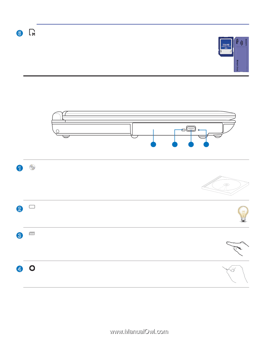
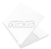
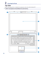
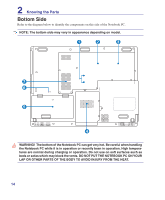
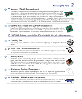
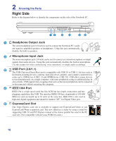
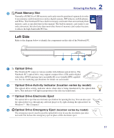
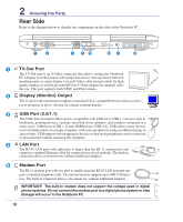
2 Knowing the Parts 6 Flash Memory Slot Normally a PCMCIA or USB memory card reader must be purchased separately in order to use memory cards from devices such as digital cameras, MP3 players, mobile phones, and PDAs. This Notebook PC has a built-in memory card reader that can read many flash memory cards as specified later in this manual. The built-in memory card reader is not only convenient, but also faster than most other forms of memory card readers because it utilizes the high-bandwidth PCI bus. Left Side Refer to the diagram below to identify the components on this side of the Notebook PC. 1 2 34 1 Optical Drive The Notebook PC comes in various models with different optical drives. The Notebook PC's optical drive may support compact discs (CD) and/or digital video discs (DVD) and may have recordable (R) or re-writable (RW) capabili- ties. See the marketing specifications for details on each model. 2 Optical Drive Activity Indicator (location varies by model) The optical drive activity indicator shows when data is being transferred by the optical disk drive. This indicator will light in proportion to the data size transferred. 3 Optical Drive Electronic Eject The optical drive eject has an electronic eject button for opening the tray. You can also eject the optical drive tray through any software player or by right clicking the optical drive in Windows™ "My Computer." 4 Optical Drive Emergency Eject (location varies by model) The emergency eject is used to eject the optical drive tray in case the electronic eject does not work. Do not use the emergency eject in place of the electronic eject. 17
-
 1
1 -
2
-
3
-
4
-
5
-
6
-
7
-
8
-
9
-
10
-
11
-
 12
12 -
 13
13 -
 14
14 -
 15
15 -
 16
16 -
 17
17 -
 18
18 -
 19
19 -
 20
20 -
 21
21 -
 22
22 -
23
-
24
-
25
-
26
-
27
-
28
-
29
-
30
-
31
-
32
-
33
-
34
-
35
-
36
-
37
-
38
-
39
-
40
-
41
-
42
-
43
-
44
-
45
-
46
-
47
-
48
-
49
-
50
-
51
-
52
-
53
-
54
-
55
-
56
-
57
-
58
-
59
-
60
-
61
-
62
-
63
-
64
-
65
-
66
-
67
-
68
-
69
-
70
 |
 |