Asus T2-AE1 T2-AE1 User''s Manual for English
Asus T2-AE1 Manual
 |
View all Asus T2-AE1 manuals
Add to My Manuals
Save this manual to your list of manuals |
Asus T2-AE1 manual content summary:
- Asus T2-AE1 | T2-AE1 User''s Manual for English - Page 1
Terminator 2 Barebone System Model T2-AE1 - Asus T2-AE1 | T2-AE1 User''s Manual for English - Page 2
, without the express written permission of ASUSTeK COMPUTER INC. ("ASUS"). Product warranty or service will not be extended if: (1) the AS A COMMITMENT BY ASUS. ASUS ASSUMES NO RESPONSIBILITY OR LIABILITY FOR ANY ERRORS OR INACCURACIES THAT MAY APPEAR IN THIS MANUAL, INCLUDING THE PRODUCTS AND - Asus T2-AE1 | T2-AE1 User''s Manual for English - Page 3
Table of contents Notices vi Safety information vii About this guide viii System package contents x Chapter 1: System Introduction 1.1 Welcome CPU 2-5 2.6 Installing the CPU fan and heatsink assembly 2-7 2.7 Installing a DIMM 2-8 2.7.1 Memory configurations 2-8 2.7.2 DIMM installation 2-10 - Asus T2-AE1 | T2-AE1 User''s Manual for English - Page 4
the support CD 3-3 3.3.2 Drivers menu 3-3 3.3.3 Utilities menu 3-4 3.3.4 ASUS contact information 3-6 3.3.5 Other information 3-6 3.4 Software information 3-7 3.4.1 ASUS Instant Music 3-7 3.4.2 ASUS Radio Player 3-9 Chapter 4: Motherboard Info 4.1 Introduction 4-2 4.2 Motherboard layout - Asus T2-AE1 | T2-AE1 User''s Manual for English - Page 5
Music Configuration 5-27 5.5 Power menu 5-28 5.5.1 Suspend Mode 5-28 5.5.2 Repost Video on S3 Resume 5-28 5.5.3 ACPI 2.0 Support 5-28 5.5.4 ACPI APIC Support 5-28 5.5.5 APM Configuration 5-29 5.5.6 Hardware Monitor 5-30 5.6 Boot menu 5-32 5.6.1 Boot Device Priority 5-32 5.6.2 Boot Settings - Asus T2-AE1 | T2-AE1 User''s Manual for English - Page 6
. This equipment generates, uses and can radiate radio frequency energy and, if not installed and used in accordance with manufacturer's instructions, may cause harmful interference to radio communications. However, there is no guarantee that interference will not occur in a particular installation - Asus T2-AE1 | T2-AE1 User''s Manual for English - Page 7
in any area where it may become wet. Place the product on a stable surface. • If you encounter technical problems with the product, contact a qualified service technician or your retailer. Lithium-Ion Battery Warning C A U T I O N: Danger of explosion if battery is incorrectly replaced. Replace only - Asus T2-AE1 | T2-AE1 User''s Manual for English - Page 8
About this guide Audience This guide provides general information and installation instructions about the ASUS Terminator 2 barebone system. This guide is intended for experienced users and integrators with hardware knowledge of personal computers. How this guide is organized This guide contains the - Asus T2-AE1 | T2-AE1 User''s Manual for English - Page 9
T : Instructions that you MUST follow to complete a task. N O T E : Tips and additional information to aid in completing a task. Where to find more information Refer to the following sources for additional information and for product and software updates. 1. ASUS Websites The ASUS websites worldwide - Asus T2-AE1 | T2-AE1 User''s Manual for English - Page 10
n e s y s t e m with • ASUS motherboard • 200 W Passive PFC power supply unit • 10/100 Mbps Ethernet LAN port • CPU fan and heatsink assembly • 2 x 5.25" drive bays • drive cable • Floppy disk drive cable 3 . Support CD 4 . User guide 5 . Optional items • Optical drive (CD-ROM/CD-RW/DVD-ROM/DVD - Asus T2-AE1 | T2-AE1 User''s Manual for English - Page 11
System introduction Chapter 1 This chapter gives a general description of the ASUS Terminator 2. The chapter lists the system features including introduction on the front and rear panel, and internal components. ASUS T2-AE1 - Asus T2-AE1 | T2-AE1 User''s Manual for English - Page 12
feature. The system comes in a stylish mini-tower casing, and powered by the ASUS motherboard that supports the AMD Athlon™ 64/Athlon™ XP processor with 800 MHz FSB and up to 2 GB system memory. Supporting up to six USB 2.0 ports and Ethernet LAN, Terminator 2 offers extensive connectivity, digital - Asus T2-AE1 | T2-AE1 User''s Manual for English - Page 13
up when data is being read from or written to the hard disk drive 8 . F r o n t p a n e l I / O d o o r . Open this door to show the front panel input/output ports. ASUS T2-AE1 1-3 - Asus T2-AE1 | T2-AE1 User''s Manual for English - Page 14
drive. 1 1 . H e a d p h o n e p o r t . This port connects a headphone with a stereo mini-plug. 1 2 . M i c r o p h o n e p o r t . This Mic (pink) port connects a -speed connectivity for IEEE 1394a-compliant audio/video devices, storage peripherals, and other PC devices. 1 5 . 6 - p i n I E E E 1 - Asus T2-AE1 | T2-AE1 User''s Manual for English - Page 15
a l S / P D I F p o r t . This port connects your audio system for 5.1-channel surround sound and enhanced 3D audio. 3 . S e r i a l p o r t . This port connects a mouse, connects a headphone or a speaker. In 4/6-channel mode, the function of this port becomes Front Speaker Out. ASUS T2-AE1 1-5 - Asus T2-AE1 | T2-AE1 User''s Manual for English - Page 16
network hub. 1 3 . E x p a n s i o n s l o t c o v e r s. Remove these cover when installing expansion cards. 1 4 . C h a s s i s f a n v e n t . This vent is for the fan that provides ventilation inside the system chassis. 1 5 . P o w e r s u p p l y u n i t f a n v e n t . This vent is for the PSU - Asus T2-AE1 | T2-AE1 User''s Manual for English - Page 17
(optional) 2. 5.25-inch empty optical drive bay 3. Floppy disk drive (optional) 4. Front panel cover 5. Hard disk drive metal tray 6. Chassis fan 7. ASUS motherboard 8. DIMM sockets 9. CPU heatsink and fan 10. AGP slot 11. PCI slot 12. Serial ATA connectors 13. Expansion card slots ASUS T2-AE1 1-7 - Asus T2-AE1 | T2-AE1 User''s Manual for English - Page 18
1-8 Chapter 1: System introduction - Asus T2-AE1 | T2-AE1 User''s Manual for English - Page 19
Basic installation Chapter 2 This chapter provides step-by-step instructions on how to install components in the system. ASUS T2-AE1 - Asus T2-AE1 | T2-AE1 User''s Manual for English - Page 20
Inline Memory Module (DIMM) 3. Expansion card(s) 4. Hard disk drive 5. Optical drive 6. Floppy disk drive Tool Phillips (cross) screw driver grounded antistatic pad or in the bag that came with the component. The motherboard comes with an onboard standby power LED. This LED lights up to indicate - Asus T2-AE1 | T2-AE1 User''s Manual for English - Page 21
the 1 cover to the chassis. 1 1 2. Use a Phillips screw driver to remove the cover screws. Keep the screws for later use. 2 3. Slightly pull the cover toward the rear panel until the side tabs are disengaged from the chassis. 4. Lift the cover, then set aside. 2 2 4 3 3 ASUS T2-AE1 2-3 - Asus T2-AE1 | T2-AE1 User''s Manual for English - Page 22
for about half an inch. 6. Slightly lift the PSU. 7. Disconnect the power plugs on the motherboard, then set the PSU aside. When removing the PSU, make sure to hold or support it firmly. The unit may accidentally drop and damage other system components. 5 7 7 2-4 Chapter 2: Basic installation - Asus T2-AE1 | T2-AE1 User''s Manual for English - Page 23
2.5 Installing a CPU The motherboard comes with a surface mount 754-pin Zero Insertion Force (ZIF) socket designed for the AMD Athlon™ 64 processor in the 754-pin lidded ceramic micro PGA package. Take note a CPU: 1. Locate the 754-pin ZIF socket on the motherboard. ® CPU Socket 775 ASUS T2-AE1 2-5 - Asus T2-AE1 | T2-AE1 User''s Manual for English - Page 24
lever to secure the CPU. The lever clicks on the side tab to indicate that it is locked. 6. Install a CPU heatsink and fan following the instructions that came with the heatsink package. 7. Connect the CPU fan cable to the CPU_FAN connector on the motherboard. 2-6 Chapter 2: Basic installation - Asus T2-AE1 | T2-AE1 User''s Manual for English - Page 25
fits the retention module. 3. Connect the CPU fan cable to the CPU fan connector on the motherboard. 4. Align the metal clips to the side rail of the CPU fan and heatsink assembly, with the locking levers in its end into the hole of the retention module. Hook Metal clip 6 6 ASUS T2-AE1 2-7 - Asus T2-AE1 | T2-AE1 User''s Manual for English - Page 26
2.7 Installing a DIMM The system motherboard comes with two Double Data Rate (DDR) Dual Inline Memory Module (DIMM) sockets. The following figure illustrates the location of the sockets: DIMM1 DIMM2 104 Pins 80 Pins ® 184-pin DDR DIMM sockets 2.7.1 Memory configurations You may install up to 2 - Asus T2-AE1 | T2-AE1 User''s Manual for English - Page 27
Recommended memory configurations Mode Single-channel DIMM1 (1) Installed (2) - (3)* Installed Sockets DIMM2 - Installed ASUS qualified vendors. Refer to the Qualified DDR400 vendors list on this page. Visit the ASUS website (www.asus.com) for the latest DDR Qualified Vendors List. ASUS T2-AE1 - Asus T2-AE1 | T2-AE1 User''s Manual for English - Page 28
2.7.2 DIMM installation To install a DDR DIMM. 1. Locate the two DIMM sockets on the motherboard. 2. Unlock a socket by pressing the retaining clips outward. 3. Align a DIMM on the socket such that the notch on the DIMM matches the break on the - Asus T2-AE1 | T2-AE1 User''s Manual for English - Page 29
so may cause you physical injury and damage the motherboard. 2.8.1 Expansion slots PCI slot The PCI slot supports PCI cards such as a LAN card, SCSI card your motherboard. ® Floppy Accelerated Graphics Port (AGP) Keyed for 1.5v Install only 1.5V AGP cards on this motherboard! ASUS T2-AE1 2-11 - Asus T2-AE1 | T2-AE1 User''s Manual for English - Page 30
2.8.3 Expansion card installation To install an expansion card. 1. Before installing the expansion card, read the documentation that came with it and make the necessary hardware settings for the card. 2. Pull the expansion card lock to the direction of the arrow. 2 Expansion PCI AGP 8x slot card - Asus T2-AE1 | T2-AE1 User''s Manual for English - Page 31
-- -- -- -- F shared GH shared When using a PCI card on shared slots, ensure that the drivers support "Share IRQ" or that the cards do not need IRQ assignments; otherwise, conflicts will arise between the two PCI groups, making the system unstable and the card inoperable. ASUS T2-AE1 2-13 - Asus T2-AE1 | T2-AE1 User''s Manual for English - Page 32
2.9 Installing an optical drive The Terminator 2 system comes with two 5.25-inch drive bays for two optical drives. • You may install a second optical drive only if you installed a Serial ATA hard - Asus T2-AE1 | T2-AE1 User''s Manual for English - Page 33
connector (blue connector labeled PRI_IDE) on the motherboard. See page 4-8 for the location of the primary IDE connector. 12. Connect the other end of the audio cable to the 4-pin CD1 connector on the motherboard. See page 4-10 for the location of the CD audio connector. 7 8 9 ASUS T2-AE1 2-15 - Asus T2-AE1 | T2-AE1 User''s Manual for English - Page 34
13. Reinstall the front panel cover by aligning its hooks with the chassis holes. 14. Lock the front panel cover hooks to the chassis holes as indicated. 13 14 2-16 Chapter 2: Basic installation - Asus T2-AE1 | T2-AE1 User''s Manual for English - Page 35
floppy disk drive connector (labeled FLOPPY) on the motherboard. See page 4-10 for the connector location. 6. Connect a power cable from the power supply unit to the power connector at the back of the floppy disk drive. See page 2-21 for details on the power supply unit plugs. ASUS T2-AE1 6 4 2-17 - Asus T2-AE1 | T2-AE1 User''s Manual for English - Page 36
disk drive (HDD) The system supports one Ultra ATA/133 IDE or one Serial ATA hard disk drive. To install an IDE hard disk drive: 1. Locate the HDD tray lock screw on the other side of the chassis. 2. Remove the lock screw with a Philips screw driver. Keep the screw for later use - Asus T2-AE1 | T2-AE1 User''s Manual for English - Page 37
on the motherboard. See page 4-9 for the location of the Serial ATA connectors. 3. Connect the 15-pin SATA power adapter plug to the power connector at the back of the drive, then connect the other end (4-pin male) to a 4-pin (female) power plug from the power supply unit. ASUS T2-AE1 2-19 - Asus T2-AE1 | T2-AE1 User''s Manual for English - Page 38
the PSU with the screw you removed earlier. Make sure the PSU cables do 6 not interfere with the CPU and/or chassis fans. 5 6. Connect the 20-pin ATX power plug to the ATXPWR connector on the motherboard. See page 4-8 for the location of this connector. 2-20 Chapter 2: Basic installation - Asus T2-AE1 | T2-AE1 User''s Manual for English - Page 39
in your area is 200-240 V, set the switch to 230 V. 11 5 Setting the switch to 115 V in a 230 V environment will seriously damage the system! ASUS T2-AE1 2-21 - Asus T2-AE1 | T2-AE1 User''s Manual for English - Page 40
2.13 Replacing the cover To replace the cover: 1. Turn the chassis upright. 3 2. Position the front edge of the cover at least two inches from the front panel cover. Fit the cover tabs with the chassis rail and the front panel tabs. 3. Lower the rear edge of the cover as shown. 4. Push the cover - Asus T2-AE1 | T2-AE1 User''s Manual for English - Page 41
2.14 Connecting external devices To the front panel Headphone Mic Scanner Camera HDD ASUS T2-AE1 2-23 - Asus T2-AE1 | T2-AE1 User''s Manual for English - Page 42
To the rear panel Joystick Serial mouse PS/2 KB VGA monitor Recorder Card reader RJ-45 Mic P S/2 Mouse Printer Line Out Po w e r outlet 2-24 Chapter 2: Basic installation - Asus T2-AE1 | T2-AE1 User''s Manual for English - Page 43
Chapter 3 This chapter helps you power up the system and install drivers and utilities from the support CD. ASUS T2-AE1 Starting up - Asus T2-AE1 | T2-AE1 User''s Manual for English - Page 44
3.1 Installing an operating system Terminator 2 supports Windows® 2000/XP/2003 (32-bit) operating systems (OS). Always install the latest OS version and corresponding updates so you can maximize the features of your hardware. Because motherboard settings and hardware options vary, use the setup - Asus T2-AE1 | T2-AE1 User''s Manual for English - Page 45
installed devices. Install the necessary drivers to activate the devices. SiS AGP Driver Installs the SiS AGP driver. SiS Graphics Adapter Drivers Installs the SiS graphics adapter drivers. Realtek AC`97 Drivers Applications Installs the Realtek® AC`97 drivers and applications. ASUS T2-AE1 3-3 - Asus T2-AE1 | T2-AE1 User''s Manual for English - Page 46
the CPU speed, voltage, and power combination that matches the user's performance requirements. USB 2.0 Driver Click this item to install the USB 2.0 driver. 3.3.3 Utilities menu The Utilities menu shows the applications and other software that the motherboard supports. 3-4 Chapter 3: Starting up - Asus T2-AE1 | T2-AE1 User''s Manual for English - Page 47
on any detected problems. This utility helps you keep your computer in a healthy operating condition. ASUS Update Installs the ASUS Update that allows you to update the motherboard BIOS and drivers. This utility requires an Internet connection either through a network or an Internet Service Provider - Asus T2-AE1 | T2-AE1 User''s Manual for English - Page 48
3.3.4 ASUS contact information The Contact tab displays the ASUS contact information. 3.3.5 Other information The icons on the top right side of the screen provide additional information on the motherboard and the contents of the support CD. 3-6 Chapter 3: Starting up - Asus T2-AE1 | T2-AE1 User''s Manual for English - Page 49
support CD have wizards that will conveniently guide you through the installation. View the online help or readme file that came with the software for more information. 3.4.1 ASUS Instant Music The motherboard is equipped with a BIOS automatically. A "beep" indicates this condition. ASUS T2-AE1 3-7 - Asus T2-AE1 | T2-AE1 User''s Manual for English - Page 50
To use ASUS Instant Music: 1. Connect the PC power plug to an electrical outlet. 2. Use either one of the two sets of special function keys on your keyboard to play audio CDs. These keys only function as indicated if you enabled the Instant Music item in BIOS. Instant Music function keys (Set 1) CD - Asus T2-AE1 | T2-AE1 User''s Manual for English - Page 51
® desktop. 3. The ASUS Radio Player panel appears. Station frequency Preset station list Close ASUS Radio Minimize ASUS Radio Power button Clock Increase the volume Decrease the volume Mute/Sound on button Store button Edit button Tune left Stop Scan left Tune right Scan right ASUS T2-AE1 3-9 - Asus T2-AE1 | T2-AE1 User''s Manual for English - Page 52
radio station: 1. Use the S c a n or T u n e buttons to tune into a radio station you wish to store. 2. Click the S t o r e button. A S t o r e C h a n n e l window appears. 3. Assign a C h a n n e l (preset number) to the radio station using the arrow buttons. 4. Type the station name in the field - Asus T2-AE1 | T2-AE1 User''s Manual for English - Page 53
Motherboard info Chapter 4 This chapter gives information about the motherboard that comes with the system. This chapter includes the motherboard layout, jumper settings, and connector locations. ASUS T2-AE1 - Asus T2-AE1 | T2-AE1 User''s Manual for English - Page 54
ASUS Terminator 2 motherboard comes already installed in the ASUS Terminator 2 system. This chapter provides technical information about the motherboard for future upgrades or system reconfiguration. FLOPPY 4.2 Motherboard USB56 USB78 BUZZ Flash BIOS PRI_IDE DJ_BTN SiS 965L PANEL 20.06cm - Asus T2-AE1 | T2-AE1 User''s Manual for English - Page 55
down the key during the boot process and enter BIOS setup to re-enter data. ® Clear RTC RAM CLRTC 2 1 Normal (Default) 3 2 Clear CMOS Except when clearing the RTC RAM, never remove the cap on CLRTC jumper default position. Removing the cap will cause system boot failure. ASUS T2-AE1 4-3 - Asus T2-AE1 | T2-AE1 User''s Manual for English - Page 56
for the rear USB ports. Set these jumpers to +5V to wake up the computer from S1 sleep mode (CPU stopped, DRAM refreshed, system running in low power mode 2. 1394 setting (3-pin 1394SEL) Keep the default setting (1-2) to enable support for IEEE 1394a devices. To disable, move the jumper caps to pins - Asus T2-AE1 | T2-AE1 User''s Manual for English - Page 57
USB56 connector on the motherboard is for the USB_2 connector on the front panel I/O daughterboard to support the USB 2.0 ports on support the front panel audio I/O ports. AGND +5VA BLINE_OUT_R BLINE_OUT_L MIC2 MICPWR Line out_R NC Line out_L ® Front panel audio connector FP_AUDIO ASUS T2-AE1 - Asus T2-AE1 | T2-AE1 User''s Manual for English - Page 58
the IEEE 1394a connectors on the front panel I/O daughterboard to support the front panel IEEE 1394a ports. Connect the IE1394_0 motherboard connector to the 1394_1 daughterboard connector, and connect the IE1394_1 motherboard connector to the 1394_2 daughterboard connector. ® IEEE 1394 connectors - Asus T2-AE1 | T2-AE1 User''s Manual for English - Page 59
GND ® Fan connectors CHA_FAN GND CPUFANPWR SYSFANIN Do not forget to connect the fan cables to the fan connectors. Lack of sufficient air flow within the system may damage the motherboard components. These are not jumpers! DO NOT place jumper caps on the fan connectors! ASUS T2-AE1 4-7 - Asus T2-AE1 | T2-AE1 User''s Manual for English - Page 60
, use an 80-conductor IDE cable. ® IDE connector 4-8 PRI_IDE NOTE: Orient the red markings (usually zigzag) on the IDE ribbon cable to PIN 1. PIN 1 Chapter 4: Motherboard info - Asus T2-AE1 | T2-AE1 User''s Manual for English - Page 61
GND SATA2 GND TXP2 TXN2 GND RXP2 RXN2 GND Important notes on Serial ATA • You must install Windows® 2000 Service Pack 4 or the Windows® XP Service Pack 1 before using Serial ATA hard disk drives. • When using the connectors in S t a Black Master Slave Use Boot disk Data disk ASUS T2-AE1 4-9 - Asus T2-AE1 | T2-AE1 User''s Manual for English - Page 62
audio connectors (4-pin AUX, CD) These connectors allow you to receive stereo audio input from sound sources such as a CD-ROM, TV tuner, or MPEG card. AUX CD Right Audio Channel to prevent incorrect cable connection when using an FDD cable with a covered Pin 5. 4-10 Chapter 4: Motherboard info - Asus T2-AE1 | T2-AE1 User''s Manual for English - Page 63
the system power button. Pressing the power button turns the system ON or puts the system in SLEEP or SOFT-OFF mode depending on the BIOS settings. Pressing the power switch for more than four seconds while the system is ON turns the system OFF. ASUS T2-AE1 4-11 - Asus T2-AE1 | T2-AE1 User''s Manual for English - Page 64
4-12 Chapter 4: Motherboard info - Asus T2-AE1 | T2-AE1 User''s Manual for English - Page 65
Chapter 5 This chapter tells how to change system settings through the BIOS Setup menus and describes the BIOS parameters. BIOS setup ASUS T2-AE1 1 - Asus T2-AE1 | T2-AE1 User''s Manual for English - Page 66
Updates the BIOS using a bootable floppy disk or the motherboard support CD when the BIOS file fails or gets corrupted.) 4. A S U S U p d a t e (Updates the BIOS in Windows Windows® XP environment a. Insert a 1.44 MB floppy disk to the floppy disk drive. b. Click S t a r t from the Windows® desktop, - Asus T2-AE1 | T2-AE1 User''s Manual for English - Page 67
+ during the Power-On Self Tests (POST). To update the BIOS using EZ Flash: 1. Visit the ASUS website (www.asus.com) to download the latest BIOS file for the motherboard and rename the same to K 8 S T . R O M. 2. Save the BIOS file to a floppy disk, then restart the system. 3. Press - Asus T2-AE1 | T2-AE1 User''s Manual for English - Page 68
least 600 KB free space to save the file. • The succeeding BIOS screens are for reference only. The actual BIOS screen displays may not be exactly the same as shown. 1. Copy the AFUDOS utility (afudos.exe) from the motherboard support CD to the bootable floppy disk you created earlier. 2. Boot the - Asus T2-AE1 | T2-AE1 User''s Manual for English - Page 69
Updating the BIOS file To update the BIOS file using the AFUDOS utility: 1. Visit the ASUS website (www.asus.com) and download the latest BIOS file for the motherboard. Save the BIOS file to a bootable floppy disk. Write the BIOS filename on a piece of paper. You need to type the exact BIOS filename - Asus T2-AE1 | T2-AE1 User''s Manual for English - Page 70
Please restart your computer A:\> 5.1.4 ASUS CrashFree BIOS 2 utility The ASUS CrashFree BIOS 2 is an auto recovery tool that allows you to restore the BIOS file when it fails or gets corrupted during the updating process. You can update a corrupted BIOS file using the motherboard support CD or the - Asus T2-AE1 | T2-AE1 User''s Manual for English - Page 71
optical drive for the original or updated BIOS file. The utility then updates the corrupted BIOS file. Bad BIOS checksum. Starting BIOS recovery... Checking for floppy... Floppy not found! Checking for CD-ROM... CD-ROM found! Reading file "K8ST.ROM". Completed. Start flashing... ASUS T2-AE1 5-7 - Asus T2-AE1 | T2-AE1 User''s Manual for English - Page 72
be the latest BIOS version for this motherboard. Visit the ASUS website (www.asus.com) to download the latest BIOS file. 5.1.5 ASUS Update utility The ASUS Update is a utility that allows you to manage, save, and update the motherboard BIOS in Windows® environment. The ASUS Update utility allows you - Asus T2-AE1 | T2-AE1 User''s Manual for English - Page 73
S U p d a t e. The ASUS Update main window appears. 2. Select U p d a t e B I O S f r o m 3. Select the ASUS FTP site t h e I n t e r n e t option from the nearest you to avoid network drop-down menu, then click traffic, or click A u t o S e l e c t. N e x t. Click N e x t. ASUS T2-AE1 5-9 - Asus T2-AE1 | T2-AE1 User''s Manual for English - Page 74
to download. Click Next. 5. Follow the screen instructions to complete the update process. The ASUS Update utility is capable of updating itself through the Internet. Always update the utility to avail all its features. Updating the BIOS through a BIOS file To update the BIOS through a BIOS file - Asus T2-AE1 | T2-AE1 User''s Manual for English - Page 75
under the Exit Menu. See section "5.7 Exit Menu." • The BIOS setup screens shown in this section are for reference purposes only, and may not exactly match what you see on your screen. • Visit the ASUS website (www.asus.com) to download the latest BIOS file for this motherboard. ASUS T2-AE1 5-11 - Asus T2-AE1 | T2-AE1 User''s Manual for English - Page 76
5.2.1 BIOS menu screen Menu items Menu bar Configuration fields General help System Time System Date Legacy Diskette A [16:37:21] [Thu,01/06/2005] [1.44M, 3.5 in.] Primary IDE Master : [ST320410A] Primary IDE Slave : [ASUS CD-S520/A] Onboard PCI S-ATA Controller : [Disabled] System - Asus T2-AE1 | T2-AE1 User''s Manual for English - Page 77
. Plug And Play O/S PCI Latency Timer Allocate IRQ to PCI VGA Palette Snooping PCI IDE BusMaster [No] [64] [Yes] [Disabled] [Enabled] 5.2.9 General help Pop-up window At the top right corner of the menu screen is a brief description of the selected item. Scroll bar ASUS T2-AE1 5-13 - Asus T2-AE1 | T2-AE1 User''s Manual for English - Page 78
of the basic system information. Refer to section "5.2.1 BIOS menu screen" for information on the menu screen items and /2005] [1.44M, 3.5 in.] Primary IDE Master : [ST320410A] Primary IDE Slave : [ASUS CD-S520/A] Onboard PCI S-ATA Controller : [RAID By ROM] System Information Use [ENTER - Asus T2-AE1 | T2-AE1 User''s Manual for English - Page 79
IDE Master/Slave While entering Setup, the BIOS automatically detects the presence of IDE devices. There supports multi-sector transfer feature. When set to [Disabled], the data transfer from and to the device occurs one sector at a time. Configuration options: [Disabled] [Auto] ASUS T2-AE1 - Asus T2-AE1 | T2-AE1 User''s Manual for English - Page 80
[Disabled] Enables or disables 32-bit data transfer. Configuration options: [Disabled] [Enabled] 5.3.5 Onboard PCI S-ATA Controller [RAID By ROM] Allows you to disable the onboard PC Serial ATA controller, or choose its function from the available options. Configuration options: [Disabled] [IDE By - Asus T2-AE1 | T2-AE1 User''s Manual for English - Page 81
/05 Processor Type : AMD Athlon (tm) 64 Processor 3200+ Speed : 2000 MHz Count : 1 System Memory Size : 224 MB AMI BIOS Displays the auto-detected BIOS information. Processor Displays the auto-detected CPU specification. System Memory Displays the auto-detected system memory. ASUS T2-AE1 - Asus T2-AE1 | T2-AE1 User''s Manual for English - Page 82
. CPU Configuration Chipset Onboard Devices Configuration PCI PnP Instant Music Configuration 5.4.1 CPU Configuration CPU Configuration Cool 'n' Quiet Memory Configuration [Enabled] Select Manual or Standard for Overclocking Cool 'n' Quiet [Enabled] Allows you to enable or disable the AMD Cool - Asus T2-AE1 | T2-AE1 User''s Manual for English - Page 83
Configuration CPU Configuration Burst length Memclock Mode Memory CLK CAS Latency TRCD TRP TRAS [4 Beats] Beats] [4 Beats] [2 Beats] Memclock Mode [Auto] [Auto] allows the BIOS to set the memclock mode automatically. [Limit] allows you to select from any MHz] [233 MHz] [250 MHz] ASUS T2-AE1 5-19 - Asus T2-AE1 | T2-AE1 User''s Manual for English - Page 84
WRITE Select AGP 3.0 Data Ratio Share Memory [64 MB] [AGP/Int-VGA] [Disabled] [8x] [ 32 MB] The size of mapped memory for AGP graphic data. Aperture Size [64 AGP 3.0 Data Ratio [8x] Configuration options: [8x] [4x] Share Memory [32 MB] Configuration options: [32 MB] [64 MB] 128 MB] 5-20 Chapter - Asus T2-AE1 | T2-AE1 User''s Manual for English - Page 85
[800 MHz] Configuration options: [200 MHz] [400 MHz] [600 MHz] [800 MHz] MPS Configuration MPS Configuration MPS Revision [1.4] Select MPS Revision MPS Revision [1.4] Configuration options: [1.1] [1.4] ASUS T2-AE1 5-21 - Asus T2-AE1 | T2-AE1 User''s Manual for English - Page 86
] SiS190 LAN Boot ROM [Disabled] Allows you to enable or disable the boot ROM in the onboard LAN controller. Configuration options: [Disabled] [Enabled] 5-22 Chapter 5: BIOS setup - Asus T2-AE1 | T2-AE1 User''s Manual for English - Page 87
USB controller legacy mode is enabled. If no USB device is detected, the legacy USB support is disabled. Configuration options: [Disabled] [Enabled] [Auto] USB 2.0 Controller Mode host controller interface (EHCI) hand-off support. Configuration options: [Disabled] [Enabled] ASUS T2-AE1 5-23 - Asus T2-AE1 | T2-AE1 User''s Manual for English - Page 88
you to select the Game Port adderss or to disable the port. Configuration options: [Disabled] [200/300] [200/330] [208/300] [208/330] 5-24 Chapter 5: BIOS setup - Asus T2-AE1 | T2-AE1 User''s Manual for English - Page 89
for either PCI/PnP or legacy ISA devices, and setting the memory size block for legacy ISA devices. Take caution when changing the Play operating system. Plug and Play O/S [No] When set to [No], BIOS configures all the devices in the system. When set to [Yes] and if you ASUS T2-AE1 5-25 - Asus T2-AE1 | T2-AE1 User''s Manual for English - Page 90
PCI IDE BusMaster [Enabled] Allows BIOS to use PCI bus mastering when reading/writing to IDE devices. Configuration options: [Disabled] [Enabled] OffBoard PCI/ISA to [Reserved], the IRQ is reserved for legacy ISA devices. Configuration options: [PCI Device] [Reserved] 5-26 Chapter 5: BIOS setup - Asus T2-AE1 | T2-AE1 User''s Manual for English - Page 91
Music CD-ROM drive [IDE Primary Slave] Allows you to configure the Instant Music CD-ROM selection. Configuration options: [IDE Primary Master] [IDE Primary Slave] ASUS T2-AE1 5-27 - Asus T2-AE1 | T2-AE1 User''s Manual for English - Page 92
& S3 (STR)] [S3 Only] 5.5.2 Repost Video on S3 Resume [No] Determines whether to invoke VGA BIOS POST on S3/STR resume. Configuration options: [No] [Yes] 5.5.3 ACPI 2.0 Support [No] Allows you to add more tables for Advanced Configuration and Power Interface (ACPI) 2.0 specifications. Configuration - Asus T2-AE1 | T2-AE1 User''s Manual for English - Page 93
to turn on the system. This feature requires an ATX power supply that provides at least 1A on the +5VSB lead. Configuration options: [Disabled] [Enabled] ASUS T2-AE1 5-29 - Asus T2-AE1 | T2-AE1 User''s Manual for English - Page 94
if you do not wish to display the detected temperatures. CPU Fan Speed [xxxxRPM] or [N/A] The onboard hardware monitor automatically detects and displays the CPU fan speed in rotations per minute (RPM). If the fan is not connected to the motherboard, the field shows N/A. 5-30 Chapter 5: BIOS setup - Asus T2-AE1 | T2-AE1 User''s Manual for English - Page 95
fan cable connected to the CPU fan connector. Set to [PWM] when using a 4-pin CPU fan cable. Set to [DC] when using a 3-pin CPU fan cable. Configuration options: [PWM] [DC] CPU Q-Fan Ratio [Auto] Allows you to select the appropriate CPU fan through the onboard voltage regulators. ASUS T2-AE1 5-31 - Asus T2-AE1 | T2-AE1 User''s Manual for English - Page 96
Priority 1st Boot Device 2nd Boot Device 3rd Boot Device [1st FLOPPY DRIVE] [PM-ST320410A] [PS-ASUS CD-S520/A] Specifies the boot sequence from the availabe devices. 1st ~ xxth Boot Device [1st Floppy in the system. Configuration options: [xxxxx Drive] [Disabled] 5-32 Chapter 5: BIOS setup - Asus T2-AE1 | T2-AE1 User''s Manual for English - Page 97
Support [Auto] Allows you to enable or disable support for PS/2 mouse. Configuration options: [Disabled] [Enabled] [Auto] Wait for 'F1' If Error [Enabled] When set to Enabled, the system waits for the F1 key to be pressed when error occurs. Configuration options: [Disabled] [Enabled] ASUS T2-AE1 - Asus T2-AE1 | T2-AE1 User''s Manual for English - Page 98
as in setting a user password. To clear the supervisor password, select the Change Supervisor Password then press . The message "Password Uninstalled" appears. 5-34 Chapter 5: BIOS setup - Asus T2-AE1 | T2-AE1 User''s Manual for English - Page 99
If you forget your BIOS password, you can clear it by erasing the CMOS Real Time Clock (RTC) RAM. See section "4.3 Jumpers" for information on how to erase the RTC RAM. After you have set a letters and/or numbers, then press . 3. Confirm the password when prompted. ASUS T2-AE1 5-35 - Asus T2-AE1 | T2-AE1 User''s Manual for English - Page 100
] [Enabled] 5.7 Exit menu The Exit menu items allow you to load the optimal or failsafe default values for the BIOS items, and save or discard your changes to the BIOS items. Exit Options Exit & Save Changes Exit & Discard Changes Discard Changes Load Setup Defaults Exit system setup after saving - Asus T2-AE1 | T2-AE1 User''s Manual for English - Page 101
other than System Date, System Time, and Password, the BIOS asks for a confirmation before exiting. Discard Changes This window appears. Select Y e s to load default values. Select E x i t & S a v e C h a n g e s or make other changes before saving the values to the non-volatile RAM. ASUS T2-AE1 - Asus T2-AE1 | T2-AE1 User''s Manual for English - Page 102
5-38 Chapter 5: BIOS setup - Asus T2-AE1 | T2-AE1 User''s Manual for English - Page 103
Appendix The Appendix includes the power supply unit specification for this system. ASUS T2-AE1 Appendix - Asus T2-AE1 | T2-AE1 User''s Manual for English - Page 104
Power supply specifications Input characteristics Input Voltage Range Range 1 Range 2 Input Frequency Range Maximum Input AC Current Inrush Current Efficiency Current Harmonic EPA Min Nom 90 V 115 V 180 V 230 V 47 Hz to 63 Hz 5 A max. at 115 Vac 3 A max. at 230 Vac, full load No hazards to
-
 1
1 -
 2
2 -
 3
3 -
 4
4 -
 5
5 -
 6
6 -
 7
7 -
8
-
9
-
10
-
11
-
12
-
13
-
14
-
15
-
16
-
17
-
18
-
19
-
20
-
21
-
22
-
23
-
24
-
25
-
26
-
27
-
28
-
29
-
30
-
31
-
32
-
33
-
34
-
35
-
36
-
37
-
38
-
39
-
40
-
41
-
42
-
43
-
44
-
45
-
46
-
47
-
48
-
49
-
50
-
51
-
52
-
53
-
54
-
55
-
56
-
57
-
58
-
59
-
60
-
61
-
62
-
63
-
64
-
65
-
66
-
67
-
68
-
69
-
70
-
71
-
72
-
73
-
74
-
75
-
76
-
77
-
78
-
79
-
80
-
81
-
82
-
83
-
84
-
85
-
86
-
87
-
88
-
89
-
90
-
91
-
92
-
93
-
94
-
95
-
96
-
97
-
98
-
99
-
100
-
101
-
102
-
103
-
104
 |
 |
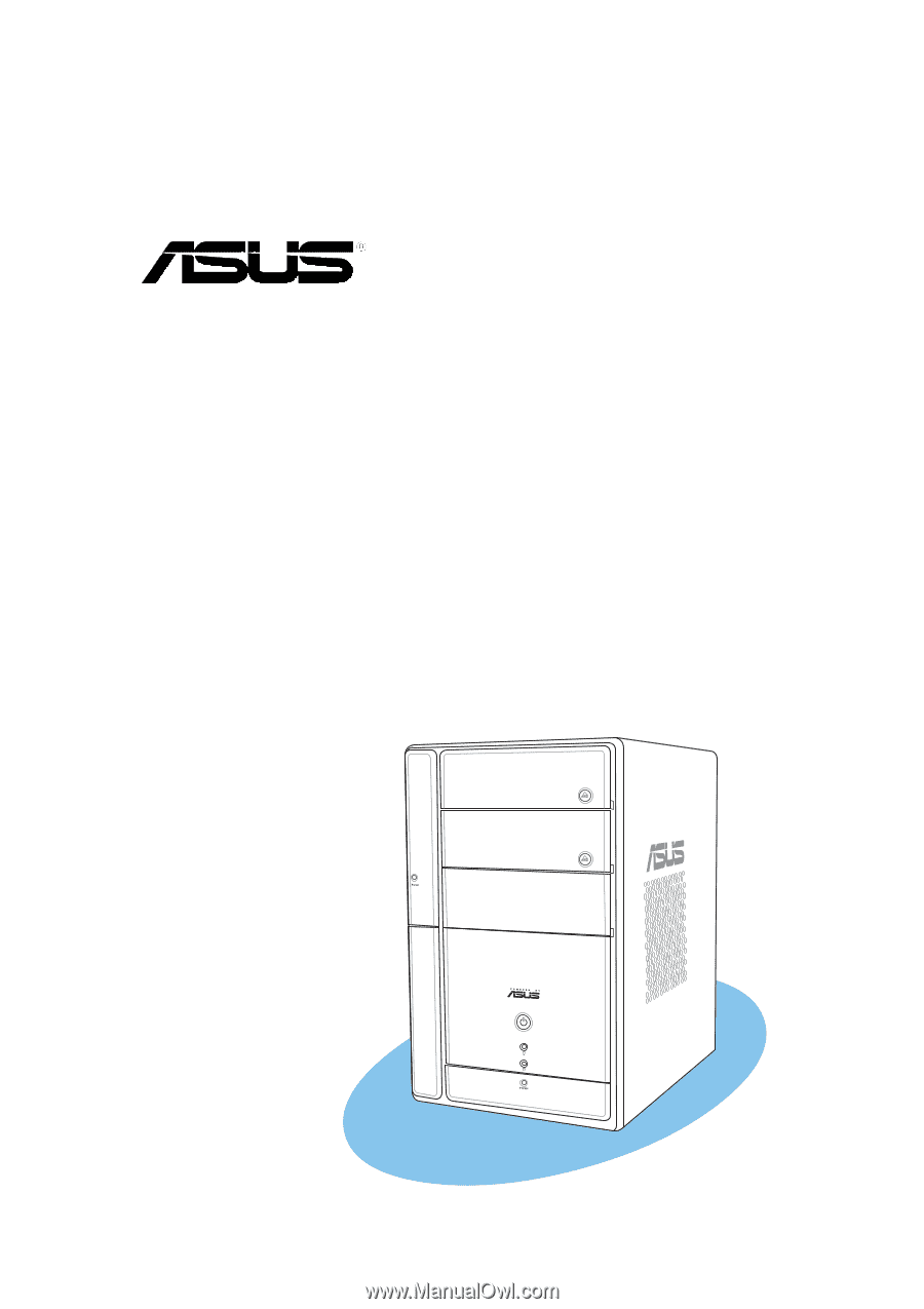
Terminator 2
Barebone System
Model T2-AE1