Asus T2-P T2-P 3-in-1 card User Manual - Page 8
User Guide. - terminator
 |
View all Asus T2-P manuals
Add to My Manuals
Save this manual to your list of manuals |
Page 8 highlights
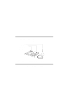
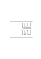
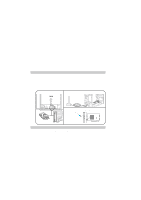
6. Connect one end of the first IEEE 1394 signal cable to the IEEE 1394 connector labeled IE1394_1 on the 3-in-1 card. 7. Connect one end of the second IEEE 1394 signal cable to the IEEE 1394 connector labeled IE1394_2 on the 3-in-1 card. 8. Connect the other end of the first IEEE 1394 signal cable to the IEEE 1394 connector labeled IE1394_1 on the front panel I/O daughterboard of the Terminator 2 system. 9. Connect the other end of the second IEEE 1394 signal cable to the IEEE 1394 connector labeled IE1394_2 on the front panel I/O daughterboard of the Terminator 2 system. 10. Replace the system cover. 89 6 7 NOTE: For details on PCI card installation, refer to "Chapter 2: Basic Installation" of the Terminator 2 User Guide. 8 ASUS T2 3-in-1 Upgrade User's Guide
-
 1
1 -
2
-
 3
3 -
 4
4 -
 5
5 -
 6
6 -
 7
7 -
 8
8 -
 9
9 -
 10
10 -
 11
11 -
 12
12 -
 13
13 -
14
-
15
-
16
-
17
-
18
-
19
-
20
-
21
-
22
-
23
-
24
 |
 |
