Asus TUEP2-M TUEP2-M User Manual - Page 40
ASUS TUEP2-M User's Manual, ATX Power Supply Connector 20-pin block ATXPWR, USB Headers 10-1 pin
 |
View all Asus TUEP2-M manuals
Add to My Manuals
Save this manual to your list of manuals |
Page 40 highlights
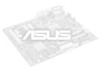
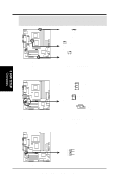
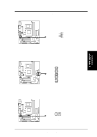
3. HARDWARE SETUP 14) USB Headers (10-1 pin USB2) If the USB Ports on the back panels are inadequate, a USB header is available for two additional USB ports. Connect the 10-1 pin ribbon cable from the provided 2-port USB connector set to the midboard 10-1 pin USB header and mount the USB connector set to an open slot on your chassis. NOTE: To use this header, make sure that the USBCNR1/USBCNR2 jumpers (see 3.4 Motherboard Settings) are set to USB Connect. 3. H/W SETUP Connectors ® TUEP2-M USB2 5 10 16 1: USB Power 2: USBP2- 3: USBP2+ 4: GND 5: NC 6: USB Power 7: USBP3- 8: USBP3+ 9: GND TUEP2-M USB Headers 15) ATX Power Supply Connector (20-pin block ATXPWR) This connector connects to an ATX power supply. The plug from the power supply will only insert in one orientation because of the different hole sizes. Find the proper orientation and push down firmly making sure that the pins are aligned. IMPORTANT: Make sure that your ATX power supply (minimum recommended wattage: 200 watts; 235W for a fully-configured system) can supply at least 20 amperes on the +5-volt lead and at least 10mA (750mA recommended) on the +5volt standby lead (+5VSB). Your system may become unstable/unreliable and may experience difficulty in powering up if your power supply is inadequate. For WakeOn-LAN support, your ATX power supply must supply at least 750mA +5VSB. ® TUEP2-M +3.3 Volts -12.0 Volts Ground Power Supply On Ground Ground Ground -5.0 Volts +5.0 Volts +5.0 Volts TUEP2-M ATX Power Connector +3.3 Volts +3.3 Volts Ground +5.0 Volts Ground +5.0 Volts Ground Power Good +5V Standby +12.0 Volts 40 ASUS TUEP2-M User's Manual
-
 1
1 -
2
-
3
-
4
-
5
-
6
-
7
-
8
-
9
-
10
-
11
-
12
-
13
-
14
-
15
-
16
-
17
-
18
-
19
-
20
-
21
-
22
-
23
-
24
-
25
-
26
-
27
-
28
-
29
-
30
-
31
-
32
-
33
-
34
-
 35
35 -
 36
36 -
 37
37 -
 38
38 -
 39
39 -
 40
40 -
 41
41 -
 42
42 -
 43
43 -
 44
44 -
 45
45 -
46
-
47
-
48
-
49
-
50
-
51
-
52
-
53
-
54
-
55
-
56
-
57
-
58
-
59
-
60
-
61
-
62
-
63
-
64
-
65
-
66
-
67
-
68
-
69
-
70
-
71
-
72
-
73
-
74
-
75
-
76
-
77
-
78
-
79
-
80
-
81
-
82
-
83
-
84
-
85
-
86
-
87
-
88
-
89
-
90
-
91
-
92
-
93
-
94
-
95
-
96
-
97
-
98
-
99
-
100
-
101
-
102
-
103
-
104
 |
 |
