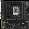
Asus TUF GAMING B760M-PLUS WIFI II Users Manual English - Page 18
Thunderbolt™ USB4, header, Q-LEDs, Thunderbolt™ I/O card that supports Intel
 |
View all Asus TUF GAMING B760M-PLUS WIFI II manuals
Add to My Manuals
Save this manual to your list of manuals |
Page 18 highlights
I2C_SCL I2C_SDA I2C_IRQ# RTD3_POWER_EN NC PERST_N WAKE# FORCE_PWR CIO_PLUG_EVENT SLP_S3# SLP_S5# GND RTD3_SW 15. Thunderbolt™ (USB4®) header The Thunderbolt™ (USB4®) header allows you to connect an add-on Thunderbolt™ I/O card that supports Intel®'s Thunderbolt™ Technology, allowing you to connect Thunderbolt™-enabled devices to form a daisychain configuration. Please visit the official website of your purchased add-on card for more details on compatibility. TB_HEADER PIN 1 The Thunderbolt™ card can only be used when installed to the PCIEX4(G4) slot. Ensure to install your Thunderbolt™ card to the PCIEX4(G4) slot. 16. Q-LEDs The Q-LEDs check key components (CPU, DRAM, VGA, and booting devices) during the motherboard booting process. If an error is found, the critical component's LED stays lit up until the problem is solved. The Q-LEDs provide the most probable cause of an error code as a starting point for troubleshooting. The actual cause may vary from case to case. 1-6 Chapter 1: Product Introduction


