Asus TX97-LE TX97-LE User Manual - Page 15
Riii. Installation
 |
View all Asus TX97-LE manuals
Add to My Manuals
Save this manual to your list of manuals |
Page 15 highlights
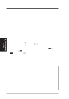
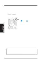
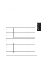
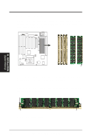
III. INSTALLATION Jumper Settings 1. Flash ROM Boot Block Programming (BBLKW) This sets the operation mode of the boot block area of the Programmable Flash ROM to allow programming in the Enabled position. This is required only if prompted by the Flash Memory Writer Utility as shown in BIOS SOFTWARE. Programming Disabled Enabled BBLKW [1-2] (Default) [2-3] BBLKW BBLKW R Disabled/Protect (Default) Enabled III. INSTALLATION (Jumpers) Boot Block Programming 2. Real Time Clock (RTC) RAM (CLRTC) The CMOS RAM is powered by the onboard button cell battery. To clear the RTC data: (1) Turn off your computer, (2) Short solder points using a small metalic object, (3) Turn on your computer, (4) Hold down during bootup and enter BIOS setup to re-enter user preferences. RTC RAM CLRTC Clear Data [short solder points momentarily] R RTC RAM (Clear Data) CLRTC Short solder points to Clear Data ASUS TX97-LE User's Manual 15
-
 1
1 -
2
-
3
-
4
-
5
-
6
-
7
-
8
-
9
-
 10
10 -
 11
11 -
 12
12 -
 13
13 -
 14
14 -
 15
15 -
 16
16 -
 17
17 -
 18
18 -
 19
19 -
 20
20 -
21
-
22
-
23
-
24
-
25
-
26
-
27
-
28
-
29
-
30
-
31
-
32
-
33
-
34
-
35
-
36
-
37
-
38
-
39
-
40
-
41
-
42
-
43
-
44
-
45
-
46
-
47
-
48
-
49
-
50
-
51
-
52
-
53
-
54
-
55
-
56
-
57
-
58
-
59
-
60
-
61
-
62
-
63
-
64
 |
 |
