Asus V3-P5945G V3-P5G945 User's Manual for English Edtion - Page 33
Remove the dummy drive slot cover from the front panel.
 |
View all Asus V3-P5945G manuals
Add to My Manuals
Save this manual to your list of manuals |
Page 33 highlights
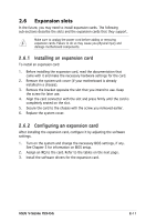
7. Connect the other end of the IDE ribbon cable to the secondary IDE connector (labeled SEC_IDE) on the motherboard. See page 4-7 for the location of this connector. 8. Remove the dummy drive slot cover from the front panel. 9. Replace the front panel. ASUS V-Series P5945G 2-15
-
 1
1 -
2
-
3
-
4
-
5
-
6
-
7
-
8
-
9
-
10
-
11
-
12
-
13
-
14
-
15
-
16
-
17
-
18
-
19
-
20
-
21
-
22
-
23
-
24
-
25
-
26
-
27
-
 28
28 -
 29
29 -
 30
30 -
 31
31 -
 32
32 -
 33
33 -
 34
34 -
 35
35 -
 36
36 -
 37
37 -
 38
38 -
39
-
40
-
41
-
42
-
43
-
44
-
45
-
46
-
47
-
48
-
49
-
50
-
51
-
52
-
53
-
54
-
55
-
56
-
57
-
58
-
59
-
60
-
61
-
62
-
63
-
64
-
65
-
66
-
67
-
68
-
69
-
70
-
71
-
72
-
73
-
74
-
75
-
76
-
77
-
78
-
79
-
80
-
81
-
82
-
83
-
84
-
85
-
86
-
87
-
88
-
89
-
90
-
91
-
92
-
93
-
94
-
95
-
96
-
97
-
98
-
99
-
100
-
101
-
102
-
103
 |
 |

2-15
ASUS V-Series P5945G
7.
Connect the other end of the IDE ribbon cable to the secondary IDE
connector (labeled SEC_IDE) on the motherboard. See page 4-7 for
the location of this connector.
8.
Remove the dummy drive slot cover from the front panel.
9.
Replace the front panel.