Asus VINTAGE-PE1 Vintage-PE1 User''s Manual for English E2012 - Page 14
Rear panel - specifications
 |
View all Asus VINTAGE-PE1 manuals
Add to My Manuals
Save this manual to your list of manuals |
Page 14 highlights
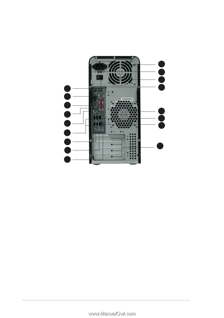
1.3 Rear panel The system rear panel includes the power connector and several I/O ports that allow convenient connection of devices. 10 11 12 1 13 2 3 14 4 15 5 16 6 7 17 8 9 1 . P S / 2 k e y b o a r d p o r t. This purple 6-pin connector is for a PS/2 keyboard. 2 . P S / 2 m o u s e p o r t. This green 6-pin connector is for a PS/2 mouse. 3 . S e r i a l p o r t . This port connects a mouse, modem, or other devices that conforms with serial specification. 4 . P a r a l l e l p o r t . This 25-pin port connects a printer, scanner, or other devices. 5 . V G A p o r t . This port connects a VGA monitor. 6 . U S B 2 . 0 p o r t s 1 , 2 , 3 a n d 4 . These 4-pin Universal Serial Bus (USB) ports are available for connecting USB 2.0 devices. 7 . M i c r o p h o n e p o r t ( p i n k ) . This port connects a microphone. 8 . L i n e O u t p o r t ( l i m e ) . This port connects a headphone or a speaker. In 4-channel, 6-channel, and 8-channel configuration, the function of this port becomes Front Speaker Out. 9 . L i n e I n p o r t ( l i g h t b l u e ) . This port connects the tape, CD, DVD player, or other audio sources. 1-4 Chapter 1: System introduction
-
 1
1 -
2
-
3
-
4
-
5
-
6
-
7
-
8
-
 9
9 -
 10
10 -
 11
11 -
 12
12 -
 13
13 -
 14
14 -
 15
15 -
 16
16 -
 17
17 -
 18
18 -
 19
19 -
20
-
21
-
22
-
23
-
24
-
25
-
26
-
27
-
28
-
29
-
30
-
31
-
32
-
33
-
34
-
35
-
36
-
37
-
38
-
39
-
40
-
41
-
42
-
43
-
44
-
45
-
46
-
47
-
48
-
49
-
50
-
51
-
52
-
53
-
54
-
55
-
56
-
57
-
58
-
59
-
60
-
61
-
62
-
63
-
64
-
65
-
66
-
67
-
68
-
69
-
70
-
71
-
72
-
73
-
74
-
75
-
76
-
77
-
78
-
79
-
80
-
81
-
82
-
83
-
84
 |
 |