Asus VW198T User Guide - Page 10
Rear of the LCD monitor
 |
UPC - 610839957354
View all Asus VW198T manuals
Add to My Manuals
Save this manual to your list of manuals |
Page 10 highlights
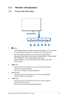
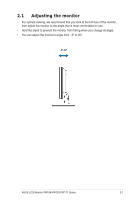
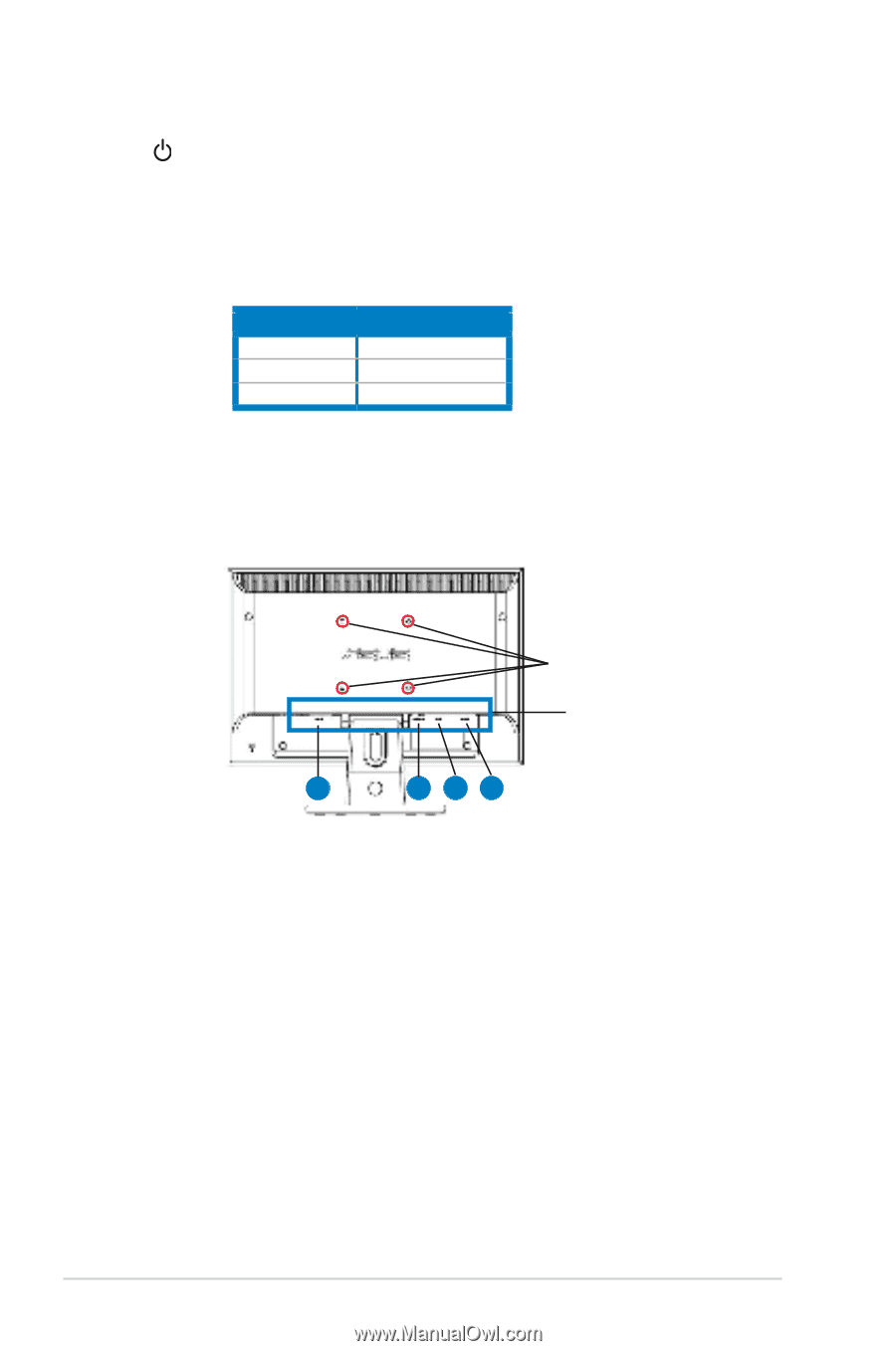
5. Power button • Press this button to turn the monitor on/off. 6. Power indicator • The color definition of the power indicator is as the below table. Status Blue Amber OFF Description ON Standby mode OFF 1.4.2. Rear.of.the.LCD.monitor. Screw.holes.for. VESA.Wall.Mount Rear.connectors 1 234 Rear.connectors.(from.left.to.right) 1. AC-IN.port. This port connects the power connector from the bundled power cord. 2. Audio-in.port. This port connects PC audio source by the bundled audio cable.(Only for some models) 3. DVI.port. This 24-pin port is for PC (Personal Computer) DVI-D digital signal connection. (Only for some models) 4. VGA.port. This 15-pin port is for PC VGA connection. 1-4 Chapter 1: Product introduction
-
 1
1 -
2
-
3
-
4
-
 5
5 -
 6
6 -
 7
7 -
 8
8 -
 9
9 -
 10
10 -
 11
11 -
 12
12 -
 13
13 -
 14
14 -
 15
15 -
16
-
17
-
18
-
19
 |
 |
1-4
Chapter 1: Product introduction
1.4.2
Rear of the LCD monitor
Rear connectors
Rear connectors (from left to right)
5.
Power button
•
Press this button to turn the monitor on/off.
6.
Power indicator
•
The color deFnition of the power indicator is as the below table.
Status
Description
Blue
ON
Amber
Standby mode
OFF
OFF
1.
AC-IN port
. This port connects the power connector from the bundled power
cord.
2.
Audio-in port
. This port connects PC audio source by the bundled audio
cable.
(
O
nly for some models)
3.
DVI port
. This 24-pin port is for PC (Personal Computer) DVI-D digital signal
connection.
(
O
nly for some models)
4.
VGA port
. This 15-pin port is for PC VGA connection.
Screw holes for
VESA Wall Mount
4
3
2
1