Asus VivoMini UN65U UN65U Users ManualEnglish
Asus VivoMini UN65U Manual
 |
View all Asus VivoMini UN65U manuals
Add to My Manuals
Save this manual to your list of manuals |
Asus VivoMini UN65U manual content summary:
- Asus VivoMini UN65U | UN65U Users ManualEnglish - Page 1
VivoMini UN65U User Manual - Asus VivoMini UN65U | UN65U Users ManualEnglish - Page 2
without intent to infringe. SPECIFICATIONS AND INFORMATION CONTAINED IN THIS MANUAL ARE FURNISHED FOR INFORMATIONAL up to the listed contract price of each product. ASUS will only be responsible for IF ASUS, ITS SUPPLIERS OR YOUR RESELLER IS INFORMED OF THEIR POSSIBILITY. SERVICE AND SUPPORT Visit - Asus VivoMini UN65U | UN65U Users ManualEnglish - Page 3
17 Turning off your VivoMini 18 Putting your VivoMini to sleep 18 Entering the BIOS Setup 18 Quickly enter the BIOS 18 Memory upgrade Upgrading memory modules 20 Appendix Safety information 28 Setting up your system 28 Care during use 28 Regulatory notices 30 ASUS contact information 36 - Asus VivoMini UN65U | UN65U Users ManualEnglish - Page 4
provides you with information on how to install new memory modules to your VivoMini. Appendix This section includes notices and safety statements for your VivoMini. Conventions used in this manual To highlight key information in this manual, some text are presented as follows: IMPORTANT! This - Asus VivoMini UN65U | UN65U Users ManualEnglish - Page 5
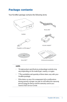
and quantity of these items vary with your VivoMini package. • If the device or any of its components fail or malfunction during normal or proper use and it is still within the warranty period, bring the device and the warranty card to you nearest ASUS Service Center. VivoMini UN Series 5 - Asus VivoMini UN65U | UN65U Users ManualEnglish - Page 6
6 VivoMini UN Series - Asus VivoMini UN65U | UN65U Users ManualEnglish - Page 7
1 Getting to know your VivoMini - Asus VivoMini UN65U | UN65U Users ManualEnglish - Page 8
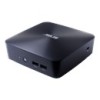
is accessing the internal storage drive. Power button The power button allows you to turn the VivoMini on or off. You can also press the power button once to put your VivoMini to sleep mode. USB 3.0 ports The USB 3.0 (Universal Serial Bus 3.0) port provides a maximum of 2A output current, transfer - Asus VivoMini UN65U | UN65U Users ManualEnglish - Page 9
Left panel Memory card slot The built-in memory card reader enables your VivoMini to read and write data to and from MMC/SD cards. Right panel The Kensington security slot allows you to secure your VivoMini using Kensington® compatible security products. NOTE: The position for this slot may vary per - Asus VivoMini UN65U | UN65U Users ManualEnglish - Page 10
supplied power adapter converts AC power to DC power for use with this jack. Power supplied through this jack supplies power to the VivoMini. To prevent damage to the VivoMini, always use the bundled power adapter. WARNING! The power adapter may become warm to hot when in use. Do not cover the - Asus VivoMini UN65U | UN65U Users ManualEnglish - Page 11
backward compatible to USB 2.0. LAN port The 8-pin RJ-45 LAN port supports a standard Ethernet cable for connection to a local network. Headphone output/microphone input combo jack port This port allows you to connect your VivoMini to amplified speakers or headphones. You can also use this port to - Asus VivoMini UN65U | UN65U Users ManualEnglish - Page 12
12 VivoMini UN Series - Asus VivoMini UN65U | UN65U Users ManualEnglish - Page 13
2 Using your VivoMini - Asus VivoMini UN65U | UN65U Users ManualEnglish - Page 14
the AC power adapter To connect the AC power adapter to your VivoMini: A. Connect the AC power cord to the AC/DC adapter. B. Plug the AC power cord into a 100 V~240 V power source. C. Connect the DC power connector into your VivoMini's power (DC) input port. NOTE: The power adapter may vary in - Asus VivoMini UN65U | UN65U Users ManualEnglish - Page 15
recommend that you use a grounded wall socket while using your VivoMini. • The socket outlet must be easily accessible and near your VivoMini. • To disconnect your VivoMini from its main power supply, unplug your VivoMini from the power socket. NOTE: Power adapter information: • Input voltage - Asus VivoMini UN65U | UN65U Users ManualEnglish - Page 16
panel You can connect a display panel or projector to your VivoMini that has the following connectors: • HDMI connector • DisplayPort connector are each sold separately. To connect a display panel to your VivoMini: Connect a display cable either to the HDMI or DisplayPort. Connecting display - Asus VivoMini UN65U | UN65U Users ManualEnglish - Page 17
USB keyboard or mouse You can connect generally any USB keyboard and mouse to your VivoMini. You can also connect a USB dongle for a wireless keyboard and mouse set. To connect a keyboard and mouse to your VivoMini: Connect the USB cable from your keyboard and mouse to any of the USB ports - Asus VivoMini UN65U | UN65U Users ManualEnglish - Page 18
system hardware settings that are needed for system startup in the VivoMini. In normal circumstances, the default BIOS settings apply to most recommend that you change the BIOS settings only with the help of a trained service personnel. Quickly enter the BIOS To quickly enter the BIOS: • Press - Asus VivoMini UN65U | UN65U Users ManualEnglish - Page 19
3 Memory upgrade - Asus VivoMini UN65U | UN65U Users ManualEnglish - Page 20
! • It is recommended that you replace the memory modules under professional supervision. Visit an ASUS service center for further assistance. • Refer to http://www.asus.com for the list of compatible DIMMs. You can only install DDR4 SO-DIMMs to the VivoMini's DIMM slots. WARNING! • Ensure that your - Asus VivoMini UN65U | UN65U Users ManualEnglish - Page 21
each rubber foot. These indicate the sequence you must follow when removing the rubber foot from its slot. Refer to the following illustration for details. VivoMini UN Series 21 - Asus VivoMini UN65U | UN65U Users ManualEnglish - Page 22
4. Remove the four screws securing the cover. 5. Get one screw from the ones you previously removed then place it into the hole. Leave a portion of the screw head that would be enough for you to hold. 22 VivoMini UN Series - Asus VivoMini UN65U | UN65U Users ManualEnglish - Page 23
6. Hold the screw then gently pull out the cover from the bottom side of the VivoMini. Use your other free hand to hold the VivoMini in place. VivoMini UN Series 23 - Asus VivoMini UN65U | UN65U Users ManualEnglish - Page 24
module into the slot (A) and press it down (B) until it is securely seated in place. Repeat the same steps to install the other memory module. IMPORTANT! Always install into the lower slot first. 8. Remove the screw you previously attached on the bottom cover (A), then align and insert the bottom - Asus VivoMini UN65U | UN65U Users ManualEnglish - Page 25
rubber foot. These indicate the sequence you must follow when replacing the rubber foot back into each slot. Refer to the following illustration for details. VivoMini UN Series 25 - Asus VivoMini UN65U | UN65U Users ManualEnglish - Page 26
26 VivoMini UN Series - Asus VivoMini UN65U | UN65U Users ManualEnglish - Page 27
Appendix VivoMini UN Series 27 - Asus VivoMini UN65U | UN65U Users ManualEnglish - Page 28
unplug the power cord from the power outlets before cleaning the system. • If you encounter the following technical problems with the product, unplug the power cord and contact a qualified service technician or your retailer. - The power cord or plug is damaged. - Liquid has been spilled into the - Asus VivoMini UN65U | UN65U Users ManualEnglish - Page 29
to the manufacturer's instructions. NO DISASSEMBLY The warranty does not apply to the products that have been disassembled by users DO NOT throw the VivoMini in municipal waste. not be placed in municipal waste. Check local technical support services for product recycling. VivoMini UN Series 29 - Asus VivoMini UN65U | UN65U Users ManualEnglish - Page 30
products at ASUS REACH website at http://csr.asus.com/english/REACH.htm ASUS Recycling/Takeback Services ASUS recycling and if not installed and used in accordance with manufacturer's instructions, may cause harmful interference to radio communications. However, turning 30 VivoMini UN Series - Asus VivoMini UN65U | UN65U Users ManualEnglish - Page 31
. RF exposure warning This equipment must be installed and operated in accordance with provided instructions and the antenna(s) used for this transmitter must be installed to provide a separation distance as in [Article 3.2] • Radio test suites according to [EN 300 328-2] VivoMini UN Series 31 - Asus VivoMini UN65U | UN65U Users ManualEnglish - Page 32
Tarn et Garonne 89 Yonne 71 Saône et Loire 75 Paris 84 Vaucluse 88 Vosges 90 Territoire de 94 Val de Marne Belfort 32 VivoMini UN Series - Asus VivoMini UN65U | UN65U Users ManualEnglish - Page 33
complies with Canadian ICES-003. IC Radiation Exposure Statement for Canada This equipment complies with IC radiation exposure limits set forth antenna during transmitting. End users must follow the specific operating instructions for satisfying RF exposure compliance. Operation is subject to - Asus VivoMini UN65U | UN65U Users ManualEnglish - Page 34
GHz Ch01 through Ch14 Europe ETSI 2.412-2.472 GHz Ch01 through Ch13 Regional notice for Singapore Complies with IDA Standards DB101867 This ASUS product complies with IDA Standards. Regional notice for California WARNING! This product may contain chemicals known to the State of California - Asus VivoMini UN65U | UN65U Users ManualEnglish - Page 35
all save money and protect the environment through energy efficient products and practices. All ASUS products with the ENERGY STAR logo comply with the ENERGY STAR standard, and the STAR joint program. NOTE: Energy Star is NOT supported on FreeDOS and Linux-based products. VivoMini UN Series 35 - Asus VivoMini UN65U | UN65U Users ManualEnglish - Page 36
Telephone +1-510-739-3777 Fax +1-510-608-4555 Web site http://usa.asus.com Technical Support Support fax General support Online support +1-812-284-0883 +1-812-282-2787 http://qr.asus.com/techserv ASUS COMPUTER GmbH (Germany and Austria) Address Harkort Str. 21-23, D-40880 Ratingen - Asus VivoMini UN65U | UN65U Users ManualEnglish - Page 37
Section 2. 1077(a) Responsible Party Name: Asus Computer International Address: 800 Corporate Way, Fremont, CA 94539. Phone/Fax No: (510)739-3777/(510)608-4555 hereby declares that the product Product Name : VivoMini Model Number : UN65U Conforms to the following specifications: FCC Part 15, Subpart - Asus VivoMini UN65U | UN65U Users ManualEnglish - Page 38
-
 1
1 -
 2
2 -
 3
3 -
 4
4 -
 5
5 -
 6
6 -
 7
7 -
8
-
9
-
10
-
11
-
12
-
13
-
14
-
15
-
16
-
17
-
18
-
19
-
20
-
21
-
22
-
23
-
24
-
25
-
26
-
27
-
28
-
29
-
30
-
31
-
32
-
33
-
34
-
35
-
36
-
37
-
38
 |
 |

VivoMini UN65U
User Manual