Asus X56VR User Manual - Page 21
Front Side, USB Port 2.0/1.1, SPDIF Output Jack, Headphone Output Jack, Microphone Input Jack
 |
View all Asus X56VR manuals
Add to My Manuals
Save this manual to your list of manuals |
Page 21 highlights
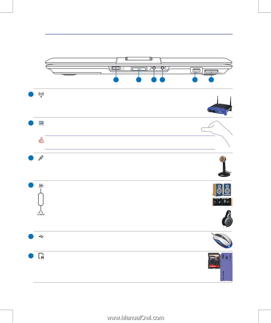
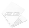
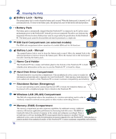
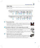
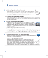
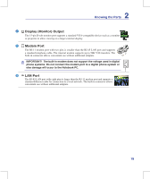
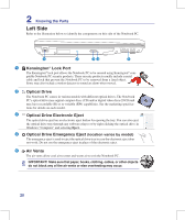
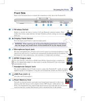
2 Knowing the Parts Front Side Refer to the illustration below to identify the components on this side of the Notebook PC. 1 2 34 5 6 1 Wireless Switch Enables or disables the built-in wireless LAN and Bluetooth (selected models). When enabled, the wireless status indicator will light. Windows software settings are necessary before use. 2 Display Panel Button Press the display panel button to open the display panel. WARNING! When opening, do not force the display panel down to the table or else the hinges may break! Never lift the Notebook PC by the display panel! 3 Microphone Input Jack The mono microphone jack (1/8 inch) can be used to connect an external microphone or output signals from audio devices. Using this jack automatically disables the built-in microphone. Use this feature for video conferencing, voice narrations, or simple audio recordings. 4 SPDIF Output Jack This jack provides connection to SPDIF (Sony/Philips Digital Interface) compliant devices for digital audio output. Use this feature to turn the Notebook PC into a hi-fi home entertainment system. Headphone Output Jack The stereo headphone jack (1/8 inch) is used to connect the Notebook PC's audio out signal to amplified speakers or headphones. Using this jack automatically disables the built-in speakers. 5 2.0 USB Port (2.0/1.1) (See other side for description.) 6 Flash Memory Slot Normally an external memory card reader must be purchased separately in order to use memory cards from devices such as digital cameras, MP3 players, mobile phones, and PDAs. This Notebook PC has a built-in high-speed memory card reader that can conveniently read from and write to many flash memory cards as mentioned later in this manual. 21 Combo
-
 1
1 -
2
-
3
-
4
-
5
-
6
-
7
-
8
-
9
-
10
-
11
-
12
-
13
-
14
-
15
-
 16
16 -
 17
17 -
 18
18 -
 19
19 -
 20
20 -
 21
21 -
 22
22 -
 23
23 -
 24
24 -
 25
25 -
 26
26 -
27
-
28
-
29
-
30
-
31
-
32
-
33
-
34
-
35
-
36
-
37
-
38
-
39
-
40
-
41
-
42
-
43
-
44
-
45
-
46
-
47
-
48
-
49
-
50
-
51
-
52
-
53
-
54
-
55
-
56
-
57
-
58
-
59
-
60
-
61
-
62
-
63
-
64
-
65
-
66
-
67
-
68
-
69
-
70
-
71
-
72
-
73
-
74
-
75
-
76
-
77
-
78
-
79
-
80
-
81
-
82
-
83
-
84
-
85
-
86
-
87
-
88
-
89
 |
 |