Asus Z62F Z62 User's Manual for English Edition (E2359) - Page 19
Front Side - manual
 |
View all Asus Z62F manuals
Add to My Manuals
Save this manual to your list of manuals |
Page 19 highlights
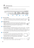
2 Knowing the Parts Front Side Refer to the diagram below to identify the components on the front side of the Notebook PC. 1 23 4 5 6 1 1 Audio Speakers The built-in stereo speaker system allows you to hear audio without additional attachments. The multimedia sound system features an integrated digital audio controller that produces rich, vibrant sound (results improved with external stereo headphones or speakers). Audio features are software controlled. 2 SPDIF Output Jack This jack provides connection to SPDIF (Sony/Philips Digital Interface) compliant devices Combo for digital audio output. Use this feature to turn the Notebook PC into a hi-fi home entertainment system. Headphone Output Jack The stereo headphone jack (1/8 inch) is used to connect the Notebook PC's audio out signal to amplified speakers or headphones. Using this jack automatically disables the built-in speakers. 3 Microphone Input Jack (Mic In) The mono microphone jack (1/8 inch) can be used to connect an external microphone or output signals from audio devices. Using this jack automatically disables the built-in microphone. Use this feature for video conferencing, voice narrations, or simple audio recordings. 4 Display Panel Latch 5 Flash Memory Slot Normally a PCMCIA or USB memory card reader must be purchased separately in order to use memory cards from devices such as digital cameras, MP3 players, mobile phones, and PDAs. This Notebook PC has a built-in memory card reader that can read many flash memory cards as specified later in this manual. The built-in memory card reader is not only convenient, but also faster than most other forms of memory card readers because it utilizes the high- bandwidth PCI bus. 6 Status Indicators Status indicator details are described in section 3. 19
-
 1
1 -
2
-
3
-
4
-
5
-
6
-
7
-
8
-
9
-
10
-
11
-
12
-
13
-
 14
14 -
 15
15 -
 16
16 -
 17
17 -
 18
18 -
 19
19 -
 20
20 -
 21
21 -
 22
22 -
 23
23 -
 24
24 -
25
-
26
-
27
-
28
-
29
-
30
-
31
-
32
-
33
-
34
-
35
-
36
-
37
-
38
-
39
-
40
-
41
-
42
-
43
-
44
-
45
-
46
-
47
-
48
-
49
-
50
-
51
-
52
-
53
-
54
-
55
-
56
-
57
-
58
-
59
-
60
-
61
-
62
-
63
-
64
-
65
-
66
-
67
-
68
-
69
-
70
 |
 |
