Asus Z97-A User Guide
Asus Z97-A Manual
 |
View all Asus Z97-A manuals
Add to My Manuals
Save this manual to your list of manuals |
Asus Z97-A manual content summary:
- Asus Z97-A | User Guide - Page 1
Z97-A Motherboard - Asus Z97-A | User Guide - Page 2
TIME WITHOUT NOTICE, AND SHOULD NOT BE CONSTRUED AS A COMMITMENT BY ASUS. ASUS ASSUMES NO RESPONSIBILITY OR LIABILITY FOR ANY ERRORS OR INACCURACIES THAT MAY APPEAR IN THIS MANUAL free by downloading it from http://support.asus.com/download or (2) for the you encounter any problems in obtaining the - Asus Z97-A | User Guide - Page 3
guide...iv Package contents...vi Z97-A specifications summary vi Chapter 1: Product Introduction 1.1 Before you proceed 1-1 1.2 Motherboard switches 1-38 1.10 Software support 1-42 Chapter 2: BIOS information 2.1 Managing and updating your BIOS 2-1 2.2 BIOS setup program 2-7 2.3 My - Asus Z97-A | User Guide - Page 4
. • If you encounter technical problems with the product, contact a qualified service technician or your retailer. About this guide This user guide contains the information you need when installing and configuring the motherboard. How this guide is organized This guide contains the following parts - Asus Z97-A | User Guide - Page 5
to the following sources for additional information and for product and software updates. 1. ASUS websites The ASUS website provides updated information on ASUS hardware and software products. Refer to the ASUS contact information. 2. Optional documentation Your product package may include optional - Asus Z97-A | User Guide - Page 6
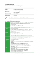
Documentation ASUS Z97-A Motherboard 3 x Serial ATA 6.0 Gb/s cables 1 x ASUS SLI bridge connector 2-in-1 Q-connector Support DVD User Guide If any of the above items is damaged or missing, contact your retailer. Z97-A specifications summary CPU Chipset Memory Expansion slots VGA LGA1150 socket - Asus Z97-A | User Guide - Page 7
Z97-A specifications summary VGA Multi-GPU Support Storage LAN Audio USB ASUS Exclusive Features - Supports Intel® InTru™ 3D, Quick Sync Video, Intel® Clear Video HD Technology, and Intel® Insider™ - Maximum shared memory of 512 MB * DisplayPort 1.2 Multi-Stream Transport compliant, supports DP - Asus Z97-A | User Guide - Page 8
, network priority, and audio scene configuration for selected applications. UEFI BIOS - Most advanced options with fast response time M.2 app for portable smartphone/tablet, supporting Android™ 4.0 and iOS® 7 systems. NFC EXPRESS 2 support (Optional) - NFC receiver ans 2-port USB 3.0 hub - NFC one - Asus Z97-A | User Guide - Page 9
ASUS Exclusive Overclocking Features Rear panel I/O ports Crystal Sound 2 - Feel the sound power with different usage scenarios Steam support - Compatible with the most fun gaming platform under Windows® system EZ DIY Push Notice - Monitor your PC status with smart devices in real time UEFI BIOS - Asus Z97-A | User Guide - Page 10
Z97-A specifications summary Rear panel I/O ports Internal I/O connectors BIOS features Manageability Support DVD Operating system support Form factor 1 x VGA port 1 x Optical S/PDIF out port 1 x Intel® LAN (RJ45) port 4 x USB 3.0/2.0 ports 2 x USB 2.0/1.1 ports 8-channel audio I/O ports 1 x 19- - Asus Z97-A | User Guide - Page 11
with the component. • Before you install or remove any component, ensure that the ATX power supply is switched off or the power cord is detached from the power supply. to secure the motherboard to the chassis. Do not overtighten the screws! Doing so can damage the motherboard. ASUS Z97-A 1-1 - Asus Z97-A | User Guide - Page 12
Place this side towards the rear of the chassis 1.2.3 Motherboard layout 1-2 Chapter 1: Product introduction - Asus Z97-A | User Guide - Page 13
EATX12V) 2. Intel® LGA1150 CPU socket 3. CPU and chassis fan connectors (4-pin CPU_FAN, 4-pin CPU_OPT; CHA_FAN1, CHA_FAN2, CHA_FAN3, CHA_FAN4) 4. DDR3 DIMM slots 5. CPU Over Voltage jumper (3-pin CPU_OV) 6. MemOK! button 7. EZ XMP switch 8. USB 3.0 connector (20-1 pin USB3_12) 9. Intel® Z97 Serial - Asus Z97-A | User Guide - Page 14
Unit (CPU) The motherboard comes with a surface mount LGA1150 socket designed for the 4th Generation and New 4th Generation Intel® Core™ i7 / Intel® Core™ i5 / Intel® Core™ i3, Pentium®, and Celeron® processors. Ensure that you install the correct CPU designed for LGA1150 socket only. DO NOT - Asus Z97-A | User Guide - Page 15
1.3.1 Installing the CPU ASUS Z97-A 1-5 - Asus Z97-A | User Guide - Page 16
1.3.2 CPU heatsink and fan assembly installation Apply the Thermal Interface Material to the CPU heatsink and CPU before you install the heatsink and fan, if necessary. To install the CPU heatsink and fan assembly 1-6 Chapter 1: Product introduction - Asus Z97-A | User Guide - Page 17
Double Data Rate 3 (DDR3) Dual Inline Memory Module (DIMM) sockets. A DDR3 module is notched differently from a DDR or DDR2 module. DO NOT install a DDR or DDR2 memory module to the DDR3 slot. According to Intel® CPU spec, DIMM voltage below 1.65 V is recommended to protect the CPU. ASUS Z97-A 1-7 - Asus Z97-A | User Guide - Page 18
overclocking may operate at a lower frequency than the vendor-marked value. To operate at the vendor-marked or at a higher frequency, refer to section 2.5 Ai Tweaker menu for manual memory frequency adjustment. • Memory modules with memory frequency higher than 2133MHz and their corresponding timing - Asus Z97-A | User Guide - Page 19
(XMP) 16GB(4 x 4GB) SS Chip NO. Timing 12-14-14-35 12-14-14-36 12-14-14-35 12-14-14-36 12-14-14-35 12-14-14-35 12-14-14-36 Voltage 1.65V 1.65V 1.65V 1.65V 1.65V 1.65V 1.65V DIMM socket support (Optional) 1 24 • • • • • • • • • • • • • • • • • • • • • ASUS Z97-A 1-9 - Asus Z97-A | User Guide - Page 20
8GB (2x4GB) SS Team TXD38G2800HC 32GB (4x8GB) DS - - 12DBK(XMP) Timing 12-14-14-35 12-14-14-36 12-14-14-36 12-13-13 14-35 12-14-14-36 12-14-14-36 12-14-14-32 11-14-14-35 Voltage 1.65V DIMM socket support (Optional) 12 4 •• • 1.65V •• • 1.65V •• 1.65V •• • 1.65V •• • 1.65V - Asus Z97-A | User Guide - Page 21
(4x4GB) DS - Chip NO. - Timing Voltage 10-11-11-31 1.65 DIMM socket support (Optional) 12 4 • • • DIMM socket support (Optional) 12 4 1.65 •• • 1.65 •• • - •• • - •• • 1.65 •• • 1.65 •• 1.65 •• • 1.65 •• • 1.65 •• • 1.65 •• • 1.65 •• 1.65 •• • 1.65 •• ASUS Z97 - Asus Z97-A | User Guide - Page 22
KHX24C11T3K4(XMP) KHX24C11T3K4/32X(XMP) 997122R(XMP) SP004GXLYU240NSA(XMP) TX2400KLN-8GK(XMP) Size SS/DS Chip Chip Timing Brand NO. 16GB (4x4GB) DS - - 9-11-11-31 Voltage DIMM socket support (Optional) 12 4 1.65 •• • 32GB (4x8GB) DS - 16GB (4x4GB) DS - - 11-13-13-31 - 10-11-11-30 - Asus Z97-A | User Guide - Page 23
8GB (2x4GB) DS - - 8GB (2x4GB) DS - - Timing 1866 9-9-9-27 9-10-9-27 9-10-9-27 9-10-9-27 9-10-9-27 9-10-9-27 Voltage DIMM socket support (Optional) 1 2 4 1.5 • • 1.5 • • • 1.5 • • • 1.5 • • • 1.5 • • • 1.5 • • 1.5 • • (continued on the next page) ASUS Z97-A 1-13 - Asus Z97-A | User Guide - Page 24
DS - - (2x4GB) Silicon SP004GXLYU186NSA(XMP) 4GB SS - - Power Silicon SP008GXLYU186NSA(XMP) 8GB DS - - Power Timing 9-10-9-27 Voltage DIMM socket support (Optional) 1 24 1.5 • • • 9-10-9-27 1.5 • • • 9-10-9-27 1.5 • • • 10-11-10-30 1.5 • • • 1866-9-10-9-27 - Asus Z97-A | User Guide - Page 25
A-DATA 3WCD-1211A 3WCD-1211A DWND-1211A Timing 11-11-11-28 11-11-11-28 9-9-9-24 Voltage - DIMM socket support (Optional) 1 2 4 • • 10-10-27 1.5 • • • - - 9-9-9- 24 1.5 • • • - - - - 11-11-11-30 - • • • 9-9-9-24 1.65 • • • (continued on the next page) ASUS Z97-A 1-15 - Asus Z97-A | User Guide - Page 26
(XMP) 8GB (2x4GB) KHX1600C9D3P1K2/8G 8GB (2x4GB) SS/DS Chip Brand Chip NO. DS - - Timing 10-1010-27 Voltage 1.5 DIMM socket support (Optional) 12 4 • • • DS - - 9-9-9-24 1.5 • • • DS - - DS - - 1600-9-9- 1.5 9-24 10-10- 1.5 10-27 • • • • • • DS - - 9-9-9-24 - Asus Z97-A | User Guide - Page 27
K4B4G0 846B K4B4G08 46B K4B4G08 46B U2S96D3 0TP-16 U2S96D3 0TP-16 Timing - Voltage 1.5 DIMM socket support (Optional) 12 4 •• • 1333-9-9-9-24 1.5 •• • - 1.5 •• • 11-11 11-11-28-1 - •• • 11-11-11-28-2 - •• • 1600-11-11-11-28 - •• • 1600-11-11-11-28 - •• • ASUS Z97-A 1-17 - Asus Z97-A | User Guide - Page 28
KFC8FNLXFDXX-15A KFC8FNLXFDXX-15A J2108ECSEDJ-F J2108BDBGGN-F J4208BBBGGN-F Timing - Voltage DIMM socket support (Optional) 1 2 4 1.5 • • • - 1.5 • • • 9 - • • • - - 9-10- - 10-26 9-9-9-24 - - - • • • • • • • • • • • • - • • • - • • • 9-9-9-24 9-9-9-24 - Asus Z97-A | User Guide - Page 29
SS SS DS SS DS Chip Brand Chip NO. Timing - - - Mach Xtreme MICRON Prtriot RiDATA RiDATA S- DIMM socket support (Optional) 1 2 4 - • • • - • • • - • • • - • • - • • • - • • • - • • • - • • • - • • • - • • • - • • • 1.4.3 DIMM installation ASUS Z97 - Asus Z97-A | User Guide - Page 30
sub‑sections describe the slots and the expansion cards that they support. Unplug the power cord before adding or removing expansion cards. Failure to do so may cause you physical injury and damage motherboard components. 1.5.1 Installing an expansion card To install an expansion card: 1. Before - Asus Z97-A | User Guide - Page 31
This motherboard supports PCI Express x16 network cards, SCSI cards, and other cards that comply with the PCI Express specifications. Slot No. Expansion slot PCIe 2.0 x1_1 slot PCIe 3.0/2.0 x16_1 slot PCI_1 slot PCIe 2.0 x1_2 slot PCIe 3.0/2.0 x16_2 slot PCI_2 slot PCIe 2.0 x16_3 slot ASUS Z97 - Asus Z97-A | User Guide - Page 32
IRQ assignments for this motherboard I.G.D. HD Audio 1 Controller HD Audio 2 Controller EHCI 1 Controller EHCI 2 Controller XHCI Controller SATA Controller PCIE x16_1 PCIE x16_2 PCIE x1_1 PCIE x1_2 Intel LAN PCI Slot 1 PCI Slot 2 A - Asus Z97-A | User Guide - Page 33
and reboot the system, then the BIOS automatically resets parameter settings to default values. • Due to chipset behavior, AC power off is required to enable C.P.R. function. You must turn off and on the power supply or unplug and plug the power cord before rebooting the system. ASUS Z97-A 1-23 - Asus Z97-A | User Guide - Page 34
2. CPU Over Voltage jumper (3-pin CPU_OV) The CPU Over Voltage jumper allows you to set a higher CPU voltage for a flexible overclocking system, depending on the type of the installed CPU. To gain more CPU voltage setting, insert the jumper to pins 2-3. To go back to its - Asus Z97-A | User Guide - Page 35
VGA port 3. USB 2.0 ports 7-8 4. PS/2 keyboard/mouse port 5. LAN port* 6. HDMI port 7. DVI-D port 8. USB 3.0 ports 56 9. USB 3.0 ports 34 10. Optical S/PDIF Out port 11. Audio I/O ports** * and **: Refer to the tables on the next page for LAN port LEDs and audio port definitions. ASUS Z97-A 1-25 - Asus Z97-A | User Guide - Page 36
USB devices must update their firmware for better compatibility. • Multi-VGA output supports up to three displays under Windows® OS environment, two displays under BIOS, and one display under DOS. • Intel display architecture design supports the following maximum supported LAN port **Audio 2, 4, 6, - Asus Z97-A | User Guide - Page 37
at the back of the system chassis. The COM module is purchased separately. 2. Intel® Z87 Serial ATA 6.0 Gb/s connectors (7-pin SATA6G_1, SATA6G_2, SATA6G_34, SATA6G_56, the SATA Mode Selection item in the BIOS to [AHCI]. See section 2.6.3 PCH Storage Configuration for details. ASUS Z97-A 1-27 - Asus Z97-A | User Guide - Page 38
may damage the motherboard components. These are not jumpers! Do not place jumper caps on the fan connectors! The CPU_FAN connector supports a CPU fan of CPU_FAN connector supports the CPU fan of maximum 1A (12 W) fan power. • The CPU_FAN connector and CHA_FAN connectors support the ASUS FAN Xpert - Asus Z97-A | User Guide - Page 39
system, we recommend that you use a power supply unit (PSU) that complies with ATX 12 V Specification 2.0 (or later version) and provides a minimum power of 350 W. Wattage Calculator at http://support.asus. com/PowerSupplyCalculator/PSCalculator.aspx?SLanguage=en-us for details. ASUS Z97-A 1-29 - Asus Z97-A | User Guide - Page 40
audio I/O module that supports either HD Audio or legacy AC`97 audio standard. Connect one end of the front panel audio I/O module cable to this connector. • We recommend that you connect a high-definition front panel audio module to this connector to avail of the motherboard's high-definition audio - Asus Z97-A | User Guide - Page 41
that supports the DirectKey function. Connect the button cable that supports DirectKey, from the chassis to this connector on the motherboard. (NGFF) SSD module. • This socket supports M Key and type 2260/2280 storage devices. • The M.2 (NGFF) SSD module is purchased separately. ASUS Z97-A 1-31 - Asus Z97-A | User Guide - Page 42
USB 2.0 specifications and supports up to 480 Mb/s connection speed. Never connect a 1394 cable to the USB connectors. Doing so will damage the motherboard! The USB 2.0 module is purchased separately. These connectors are based on xHCI specification. We recommend you to install the related driver - Asus Z97-A | User Guide - Page 43
(10-1 pin PANEL) This connector supports several chassis-mounted functions. • System speaker. The speaker allows you to hear system beeps and warnings. • ATX power button/soft-off button (2-pin PWR_SW) This connector is for the system reboot without turning off the system power. ASUS Z97-A 1-33 - Asus Z97-A | User Guide - Page 44
faster charging time for USB-chargeable devices, optimized power efficiency, and backward compatibility with USB 2.0. The USB 3.0 module is purchased separately. • These connectors are based on xHCI specification. We recommend you to install the related driver to fully use the USB 3.0 ports under - Asus Z97-A | User Guide - Page 45
and Thunderbolt cables are purchased separately. 14. T_Sensor connector (2-pin T_SENSOR1) This connector is for the thermistor cable that allows you to monitor the temperature of your motherboard's critical components and connected devices. The thermistor cable is purchased separately. ASUS Z97 - Asus Z97-A | User Guide - Page 46
and unplug the power cable before removing or plugging any motherboard components. The illustration below shows the location of the onboard LED. 2. POST State LEDs The POST State LEDs provide the status of these key components during POST (Power-On-Self Test): CPU, memory modules, VGA card, and - Asus Z97-A | User Guide - Page 47
3. TPU LED (TPU_LED) The TPU LED lights up when the TPU switch is enabled. 4. EPU LED (OLED2) The EPU LED lights up when the EPU switch is enabled. ASUS Z97-A 1-37 - Asus Z97-A | User Guide - Page 48
on a bare or open-case system. This is ideal for overclockers and gamers who continually change settings to enhance system performance. change the EPU settings in the software application or BIOS setup program and enable the EPU function at the same time. However, the system will use the last - Asus Z97-A | User Guide - Page 49
! button to boot and load the BIOS default settings. A message will appear during POST reminding you that the BIOS has been restored to its default settings. • We recommend that you download and update to the latest BIOS version from www.asus.com after using the MemOK! function. ASUS Z97-A 1-39 - Asus Z97-A | User Guide - Page 50
be activated after the next system bootup. • You may use the 5-Way Optimization and TPU feature in the AI Suite 3 application, adjust the BIOS setup program or enable the TPU switch at the same time. However, the system will use the last setting you have made. 1-40 Chapter 1: Product introduction - Asus Z97-A | User Guide - Page 51
to a power source indicating that you should shut down the system and unplug the power cable before removing or installing any motherboard component. 5. EZ XMP switch Enable this switch to overclock the installed DIMMs, allowing you to enhance the DIMM's speed and performance. ASUS Z97-A 1-41 - Asus Z97-A | User Guide - Page 52
contains the drivers, software applications, and utilities that you can install to avail all motherboard features. The contents of the Support DVD are subject to change at any time without notice. Visit the ASUS website at www.asus.com for updates. Running the support DVD Place the Support DVD into - Asus Z97-A | User Guide - Page 53
: Updates the BIOS in DOS environment using the motherboard support DVD and a USB flash disk drive. Save a copy of the original motherboard BIOS file to a USB flash disk in case you need to restore the BIOS in the future. Copy the original motherboard BIOS using the ASUS Update utility. ASUS Z97 - Asus Z97-A | User Guide - Page 54
motherboard driver, software and firmware Click or tap to search and select the BIOS file Click or tap to select a boot logo Click or tap to update the BIOS EZ Update requires an Internet connection either through a network or an ISP (Internet Service Provider). 2.1.2 ASUS EZ Flash 2 The ASUS - Asus Z97-A | User Guide - Page 55
a corrupted BIOS file using the motherboard support DVD or a USB flash drive that contains the updated BIOS file. • Before using this utility, rename the BIOS file in the removable device into Z97A.CAP. • Download the latest BIOS file from the ASUS website at http://www.asus.com. ASUS Z97-A 2-3 - Asus Z97-A | User Guide - Page 56
actually shown on your computer screen. Before updating BIOS • Prepare the motherboard support DVD and a USB flash drive. • Download the latest BIOS file and BIOS Updater from http://support.asus.com and save them in your USB flash drive. NTFS is not supported under DOS environment. Ensure that your - Asus Z97-A | User Guide - Page 57
file and BIOS Updater to the USB port. 2. Boot your computer then press to launch the select boot device screen. 3. When the select boot device screen appears, insert the Support DVD into the optical drive then select the optical drive as the boot device. Please select boot device: E1: ASUS DVD - Asus Z97-A | User Guide - Page 58
or Home/ End> keys to select the BIOS file and press . 4. After the BIOS Updater checks the selected BIOS file, select Yes to confirm the BIOS update. Are you sure you want to update the BIOS? Yes No The BIOS Backup feature is not supported due to security regulations. 5. Select Yes then - Asus Z97-A | User Guide - Page 59
as what you see on your screen. • Visit the ASUS website at www.asus.com to download the latest BIOS file for this motherboard. • Ensure that a USB mouse is connected to your motherboard if you want to use the mouse to control the BIOS setup program. • If the system becomes unstable after changing - Asus Z97-A | User Guide - Page 60
modes Selects the display language Creates storage RAID and of the BIOS setup program configures system overclocking Enables or disables the Intel Rapid Storage Technology Displays the CPU Fan's speed. Click the button to manually tune the fans Loads optimized default settings Shows the bootable - Asus Z97-A | User Guide - Page 61
BIOS time settings Menu bar Language MyFavorite Q-Fan control EZ Tuning Wizard Quick Note Hot Keys Sub-menu item Menu items General help Configuration fields Scroll bar Last modified settings Goes back to EZ Mode Displays the CPU/motherboard temperature, CPU and memory voltage output ASUS Z97 - Asus Z97-A | User Guide - Page 62
basic system configuration For changing the overclocking settings For changing the advanced system time settings. Language This button above the menu bar contains the languages that you can select for your BIOS. Click this button to select the the language that you want to display in your BIOS - Asus Z97-A | User Guide - Page 63
to change the motherboard's SATA mode from AHCI to RAID mode. Refer to section 2.2.4 EZ Tuning Wizard for more information. Quick Note (F9) This button above the menu bar allows you to key in notes of the activities that you have done in BIOS. • The Quick Note function does not support the following - Asus Z97-A | User Guide - Page 64
Control allows you to set a fan profile or manually configure the operating speed of your CPU and chassis Click to undo the changes Select to manually configure your fans Configuring fans manually Select Manual from the list of profiles to manually configure your fans' operating speed. Speed - Asus Z97-A | User Guide - Page 65
Exit (ESC). 2.2.4 EZ Tuning Wizard EZ Tuning Wizard allows you to overclock your CPU and DRAM, computer usage, and CPU fan to their best keyboard or click EZ Tuning Wizard screen, then click Next. from the BIOS screen to open 2. Select a PC scenario Daily Computing or Gaming/Media ASUS Z97-A 2-13 - Asus Z97-A | User Guide - Page 66
> on your keyboard or click EZ Tuning Wizard screen. 2. Click RAID then click Next. from the BIOS screen to open • Ensure that your HDDs have no existing RAID volumes. • Ensure to connect your HDDs to Intel® SATA connectors. 3. Select the type of storage for your RAID Easy Backup or Super Speed - Asus Z97-A | User Guide - Page 67
My Favorites To add BIOS items: 1. Press on your keyboard or click Setup Tree Map screen. from the BIOS screen to open 2. On the Setup Tree Map screen, select the BIOS items that you want to save in MyFavorites screen. Main menu panel Submenu panel Selected shortcut items ASUS Z97-A 2-15 - Asus Z97-A | User Guide - Page 68
Security The Security menu items allow you to change the system security settings. • If you have forgotten your BIOS password, erase the CMOS Real Time Clock (RTC) RAM to clear the BIOS password. See section Jumpers for information on how to erase the RTC RAM. • The Administrator or User Password - Asus Z97-A | User Guide - Page 69
for accessing the system. Otherwise, you might be able to see or change only selected fields in the BIOS setup program. To set an administrator password: 1. Select the Administrator Password item and press . , the User Password item on top of the screen shows Not Installed. ASUS Z97-A 2-17 - Asus Z97-A | User Guide - Page 70
options for this section vary depending on the CPU and DIMM model you installed on the motherboard. Scroll down to display other BIOS items. 2.5.1 Ai Overclock Tuner [Auto] This item allows you to select the CPU overclocking options to achieve the desired CPU internal frequency. Select any - Asus Z97-A | User Guide - Page 71
item appears only when you set the Ai Overclocking Tuner to [X.M.P.]. eXtreme Memory Profile This item allows you to select the X.M.P. mode supported by your memory module. Configuration options: [Profile #1] [Profile #2] 2.5.2 ASUS MultiCore Enhancement [Auto] [Auto] [Disabled] This item allows - Asus Z97-A | User Guide - Page 72
to apply the CPU default Turbo Ratio setting or manually assign a 4-Core Limit value that must be higher the minimum possible ratio on the Uncore part of the processor. Use the or keys to adjust the CPUs to get the extreme overclocking capability. Configuration options: [Auto BIOS information - Asus Z97-A | User Guide - Page 73
10 Max. CPU Graphics Ratio [Auto] [Auto] [Manual] This option allows you to automatically optimize the CPU Graphics ] This item allows you to automatically overclock the CPU and DRAM frequencies and voltage Timings DRAM CAS# Latency [Auto] Configuration options: [Auto] [1] - [31] ASUS Z97-A 2-21 - Asus Z97-A | User Guide - Page 74
DRAM WRITE Recovery Time [Auto] Configuration options: [Auto] [1] - [16] DRAM READ to PRE Time [Auto] Configuration options: [Auto] [1] - [15] DRAM FOUR ACT WIN Time [Auto] Configuration control DRAM RTL Initial Value [Auto] Configuration options: [Auto] [1] - [63] 2-22 Chapter 2: BIOS information - Asus Z97-A | User Guide - Page 75
] DRAM IO-L (CHB_R0D1) [Auto] Configuration options: [Auto] [1] - [15] DRAM IO-L (CHB_R1D0) [Auto] Configuration options: [Auto] [1] - [15] DRAM IO-L (CHB_R1D1) [Auto] Configuration options: [Auto] [1] - [15] Third Timings tRDRD [Auto] Configuration options: [Auto] [1] - [7] ASUS Z97-A 2-23 - Asus Z97-A | User Guide - Page 76
boot. Configuration options: [Auto] [Enabled] [Disabled] DRAM CLK Period [Auto] This item allows you to set a DRAM clock period. Configuration options: [Auto] [1] - [14] 2-24 Chapter 2: BIOS information - Asus Z97-A | User Guide - Page 77
CPU Load-line Calibration [Auto] Load-line is defined by Intel® specification and affects CPU power voltage. The CPU working voltage decreases proportionally to CPU loading. Higher load-line calibration could get higher voltage and good overclocking performance, but increases the CPU and VRM thermal - Asus Z97-A | User Guide - Page 78
Manual] to configure a higher frequency for a quicker transient response speed. Configuration options: [Auto] [Manual to [Manual]. Fixed CPU every VRM phase and the thermal conditions of every overclocking. A higher value setting provides higher power consumption delivery and extends the overclocking - Asus Z97-A | User Guide - Page 79
Intel SpeedStep Technology [Enabled] This item allows the operating system to dynamically adjust the processor you to limit the Turbo Ratio's time duration that exceeds the TDP (Thermal Design to prevent frequency and power throttling when overclocking. Use the or keys to ASUS Z97-A 2-27 - Asus Z97-A | User Guide - Page 80
item when overclocking. Configuration work in high performance at all times. Configuration options: [Auto] Voltage Regulator as the processor goes into low current state Integrated Voltage Regulator when it enters manual override mode. Configuration options: [Auto Chapter 2: BIOS information - Asus Z97-A | User Guide - Page 81
] The following item appears only when you set the CPU Core Voltage to [Manual]. CPU Core Voltage Override [Auto] This item allows you to set the CPU Core Voltage override. Use the or keys to adjust the value, The values range from 0.001V to 1.920 V with a 0.001 V interval. ASUS Z97-A 2-29 - Asus Z97-A | User Guide - Page 82
frequency. Configuration options: [Auto] [Manual Mode] [Offset Mode] The following item appears only when you set the CPU Cache Voltage to [Manual Mode]. CPU Cache Voltage Override [Auto iGPU frequency value. Configuration options: [Auto] [Manual Mode] [Offset Mode] [Adaptive Mode] 2-30 Chapter - Asus Z97-A | User Guide - Page 83
the CPU Core Voltage to [Manual]. CPU Graphics Voltage Override [Auto PCIE controller and the PCU (power control unit). Increase the voltage to enhance the overclocking capability. You can use the or keys to adjust the value. The To offset the voltage by a negative value. ASUS Z97-A 2-31 - Asus Z97-A | User Guide - Page 84
to enhance the overclocking capability. You can processor. By default, this item takes the standard value of the installed CPU. Increase the amount of voltage to enhance the overclocking Support [Auto] Set this item to [Enabled] when overclocking Intel® CPU specifications, DIMMs with voltage requirement - Asus Z97-A | User Guide - Page 85
with a 0.0125 V interval. • The values of the CPU PLL Voltage, CPU Manual Voltage, CPU Offset Voltage, iGPU Manual Voltage, iGPU Offset Voltage, DRAM Voltage, VCCSA Voltage, VCCIO Voltage, and PCH Voltage the value. The values range from 0.1 V to 1.9 V with a 0.00625 V interval. ASUS Z97-A 2-33 - Asus Z97-A | User Guide - Page 86
a 0.00625 V interval. 2.5.33 CPU Spread Spectrum [Auto] This item allows you to enhance the BCLK overclocking capability or reduce the EMI (electromagnetic disturbance) generated by the BCLK. Set this item to [Enabled] for values can cause the system to malfunction. 2-34 Chapter 2: BIOS information - Asus Z97-A | User Guide - Page 87
BIOS automatically detects. The items shown in submenu may be different due to the CPU you installed. Intel ] Active Processor Cores [ supporting OS (SuSE Linux 9.2, RedHat Enterprise 3 Update 3). Configuration options: [Disabled] [Enabled] Intel the DRAM loading time and improves the ASUS Z97-A 2-35 - Asus Z97-A | User Guide - Page 88
Power Management Configuration This item allows you to manage and configure the CPU's power. Enhanced Intel SpeedStep Technology [Enabled] This item allows your system to adjust the CPU's voltage and system. Configuration options: [Disabled] [CPU C7] [CPU C7s] 2-36 Chapter 2: BIOS information - Asus Z97-A | User Guide - Page 89
Intel Rapid Storage Technology when the partition size is greater than the Active Page Threshold size. When set to zero (0), it will go to Auto mode and checks if the partition size is enough at S3 entry. Ensure that the caching partition size is larger than the total memory size. ASUS Z97 - Asus Z97-A | User Guide - Page 90
support for a faster resume time. Configuration options: [Enabled] [Disabled] Intel Smart Connect Technology This item allows the system to support Intel AHCI allows the onboard storage driver to enable advanced Serial ATA system that shows a warning message during POST (Power-on Self Test) when an - Asus Z97-A | User Guide - Page 91
Audio [Enabled] This item allows you to enable or disable the CPU audio devices. Configuration options: [Disabled] [Enabled] DVI Port Audio Standby [Auto] This item allows you to enable the Intel® Graphics Render Standby support to reduce iGPU power when the system is idle. ASUS Z97-A 2-39 - Asus Z97-A | User Guide - Page 92
, the legacy USB support is enabled. Intel xHCI Mode [Smart Auto] [Auto] The xHCI is automatically enabled and runs at USB 3.0 mode when the xHCI driver is installed in the operating system. [Smart Auto] Upon detection, the xHCI driver supports the USB 3.0 mode during both POST and operating - Asus Z97-A | User Guide - Page 93
disable the individual USB ports. Refer to section 1.2.3 Motherboard layout for the location of the USB ports. 2.6.6 Platform the ASPM (active state power management) support for devices. [Disabled] BIOS controls the ASPM support for the device. PCI Power Management [Enabled] ASUS Z97-A 2-41 - Asus Z97-A | User Guide - Page 94
front panel audio module supports. [HD Audio] Sets the front panel audio connector (AAFP) mode to high definition audio. [AC97] Sets the front panel audio connector (AAFP) mode to legacy AC'97 SPDIF Out Type [SPDIF] [SPDIF] Sets to an SPDIF audio output. [HDMI] Sets to an HDMI audio output - Asus Z97-A | User Guide - Page 95
Intel® LAN controller. Configuration options: [Enabled] [Disabled] Serial Port Configuration The items in this menu allow you to configure your motherboard ] [Enabled (S4+S5] [Enabled (S5)] Restore AC Power Loss [Power Off] This item allows your system to go to ON Enabled] ASUS Z97-A 2-43 - Asus Z97-A | User Guide - Page 96
(Real-Time Clock) Network Stack to [Enabled]. Ipv4/Ipv6 PXE Support [Enabled] This item allows you to enable or disable the Ipv4/Ipv6 PXE wake event. Configuration options: [Disabled] [Enabled] 2.6.10 Intel item shows the connected SATA devices compatible for setting up RAID. On their BIOS information - Asus Z97-A | User Guide - Page 97
allows you to change the fan settings. Scroll down to display the other BIOS items. 2.7.1 Qfan Tuning Click this item to automatically detect the lowest speed not connected to the motherboard, the field shows N/A. Select [Ignore] if you do not wish to display the detected speed. ASUS Z97-A 2-45 - Asus Z97-A | User Guide - Page 98
fan speed for quiet CPU fan operation. [Turbo] Set to achieve maximum CPU fan speed. [Manual] Set to assign the detailed fan speed control parameters. The following items appear only when you set the . The range of the values depends on the CPU installed. 2-46 Chapter 2: BIOS information - Asus Z97-A | User Guide - Page 99
Mode, PWM Mode, or disable these Q-Fan controls from your motherboard. Configuration options: [Disabled] [DC Mode] [PWM Mode] The Manual]. Chassis Fan 1/4 Upper Temperature [70] Use the or keys to adjust the upper limit of the CPU temperature. The values range from 40°C to 90°C. ASUS Z97 - Asus Z97-A | User Guide - Page 100
source drops below the lower temperature. Configuration options: [Disabled] [Enabled] Anti Surge Support [Enabled] This item allows you to enable or disable the OVP (Over Voltage the safe range that protects the motherboard's components. Configuration options: [Disabled] [Enabled] 2-48 Chapter - Asus Z97-A | User Guide - Page 101
Initialization] All USB devices will not be available until OS boot up for a fastest POST time. All USB devices will be available during POST. This process will extend the POST time. For a faster POST time, only USB ports with keyboard and mouse connections will be detected. ASUS Z97-A 2-49 - Asus Z97-A | User Guide - Page 102
POST time, all PS/2 devices are not available until your computer enters the operating system. Network Stack Driver Support [Disabled] [Disabled] Select to skip the network stack driver from loading during POST. [Enabled] Select to load the network stack driver during POST. Next Boot after AC - Asus Z97-A | User Guide - Page 103
bootable devices and the add-on devices. [Enabled] For better compatibility, enable the CSM to fully support the non-UEFI driver add-on devices or the Windows® UEFI mode. [Disabled] Disables the CSM to fully support the non-UEFI driver add-on devices or the Windows® UEFI mode. ASUS Z97-A 2-51 - Asus Z97-A | User Guide - Page 104
network devices that you want to launch. Configuration options: [Legacy OpROM first] [UEFI driver unauthorized access and malwares during POST. OS Type [Windows UEFI mode. Microsoft® Secure Boot only supports Windows® UEFI mode. The following USB storage device. 2-52 Chapter 2: BIOS information - Asus Z97-A | User Guide - Page 105
loaders, and UEFI drivers that you can USB storage device. Append db from File This item allows you to load the additional db from a storage device so that more images can be loaded securely. The db file must be formatted as a UEFI variable structure with time-based authenticated variable. ASUS Z97 - Asus Z97-A | User Guide - Page 106
allows you to load the downloaded dbx from a USB storage device. Configuration options: [Yes] [No] Append as a UEFI variable structure with time-based authenticated variable. 2.8.12 Boot Option POST (Windows® 8 not supported). • To select the boot device during system startup, press when ASUS - Asus Z97-A | User Guide - Page 107
the current BIOS settings to the BIOS Flash, and create a profile. Key in a profile number from one to eight, press , and then select Yes. Load/Save Profile from/to USB Drive This item allows you to load or save profile from your USB drive, load and save profile to your USB drive. ASUS Z97 - Asus Z97-A | User Guide - Page 108
2.9.4 ASUS DRAM SPD Information This item allows you to view the DRAM SPD information. 2.10 Exit menu The Exit menu items allow you to load the optimal default values for the BIOS items, and save or discard your changes to the BIOS items. You can access the EZ Mode from the Exit menu. 2-56 - Asus Z97-A | User Guide - Page 109
radio frequency energy and, if not installed and used in accordance with manufacturer's instructions, may cause harmful interference to radio communications. However, there is no guarantee that y compris celles susceptibles de provoquer un fonctionnement non souhaité de l'appareil. ASUS Z97-A A-1 - Asus Z97-A | User Guide - Page 110
substances in our products at ASUS REACH website at http://csr.asus.com/english/REACH.htm. DO NOT throw the motherboard in municipal waste. This the battery should not be placed in municipal waste. ASUS Recycling/Takeback Services ASUS recycling and takeback programs come from our commitment to - Asus Z97-A | User Guide - Page 111
, WITHOUT WARRANTIES OR CONDITIONS OF ANY KIND, either express or implied. See the License for the specific language governing permissions and limitations under the License. ASUS Z97-A A-3 - Asus Z97-A | User Guide - Page 112
Telephone +1-510-739-3777 Fax +1-510-608-4555 Web site http://www.asus.com/us/ Technical Support Support fax Telephone Online support +1-812-284-0883 +1-812-282-2787 http://www.service.asus.com/ ASUS COMPUTER GmbH (Germany and Austria) Address Harkort Str. 21-23, D-40880 Ratingen - Asus Z97-A | User Guide - Page 113
A-5 ASUS Z97-A DECLARATION OF CONFORMITY Per FCC Part 2 Section 2. 1077(a) Responsible Party Name: Asus Computer International Address: 800 Corporate Way, Fremont, CA 94539. Phone/Fax No: (510)739-3777/(510)608-4555 hereby declares that the product Product Name : Motherboard Model Number : Z97-A - Asus Z97-A | User Guide - Page 114
A-6 Appendices
-
 1
1 -
 2
2 -
 3
3 -
 4
4 -
 5
5 -
 6
6 -
 7
7 -
8
-
9
-
10
-
11
-
12
-
13
-
14
-
15
-
16
-
17
-
18
-
19
-
20
-
21
-
22
-
23
-
24
-
25
-
26
-
27
-
28
-
29
-
30
-
31
-
32
-
33
-
34
-
35
-
36
-
37
-
38
-
39
-
40
-
41
-
42
-
43
-
44
-
45
-
46
-
47
-
48
-
49
-
50
-
51
-
52
-
53
-
54
-
55
-
56
-
57
-
58
-
59
-
60
-
61
-
62
-
63
-
64
-
65
-
66
-
67
-
68
-
69
-
70
-
71
-
72
-
73
-
74
-
75
-
76
-
77
-
78
-
79
-
80
-
81
-
82
-
83
-
84
-
85
-
86
-
87
-
88
-
89
-
90
-
91
-
92
-
93
-
94
-
95
-
96
-
97
-
98
-
99
-
100
-
101
-
102
-
103
-
104
-
105
-
106
-
107
-
108
-
109
-
110
-
111
-
112
-
113
-
114
 |
 |

Motherboard
Z97-A